Image forming method, image formng apparatus, intermediate transfer body, method of modifying surface of intermediate transfer body

Active Publication Date: 2006-07-13
CANON KK
View PDF25 Cites 85 Cited by
  • Summary
  • Abstract
  • Description
  • Claims
  • Application Information

AI Technical Summary

Benefits of technology

[0014] As can be seen from the above, in the ink jet printing system the use of an intermediate transfer body is advantageous in enhancing a level of freedom in the selection of

Problems solved by technology

Disadvantages of the offset printing, such as time and cost required by a printing plate production process and a vast investment needed to purchase the printing machine, have little adverse effect on the cost per printed sheet and speed because the printed matter is produced in large quantities.
As a trend is gaining momentum in recent years for information versatility and more and more diversified printed matters are printed in small quantities, a problem has surfaced that the production cost of printing plates for individual printed matters becomes relatively high.
Since the current offset printing has a long lead time, from a text preparation to a printing plate production and a printing familiarization (stabilizing of a printing machine), the production period cannot be shortened even when the number of printed copies is small.
Further, since a huge facility investment is necessary and all processes require high levels of skills, production locations are limited, which means it takes time for printed matters to be delivered to customers.
Among points in which printed matters produced by the ink jet printing are inferior to offset-printed matters are a glossiness of printed matter, a printability on thin paper, a printability on both sides of paper and a printing cost.
If printing is done on paper with a small ink absorption capability, ink may remain on the surface without being fully absorbed in paper, which may cause undesired phenomena, such as a bleeding in which the remaining ink becomes mixed with adjoining ink droplets and a beading in which previously landed ink droplets are drawn to subsequently landed ink droplets, resulting in a degradation of a printed image quality and a failure to dry properly.
Under these circumstances, it is very difficult to form an image on paper with a hi

Method used


Image

  • Image forming method, image formng apparatus, intermediate transfer body, method of modifying surface of intermediate transfer body
  • Image forming method, image formng apparatus, intermediate transfer body, method of modifying surface of intermediate transfer body
  • Image forming method, image formng apparatus, intermediate transfer body, method of modifying surface of intermediate transfer body

Examples


Example

I. First Embodiment

[0084] 1. Outline of Image Forming Device

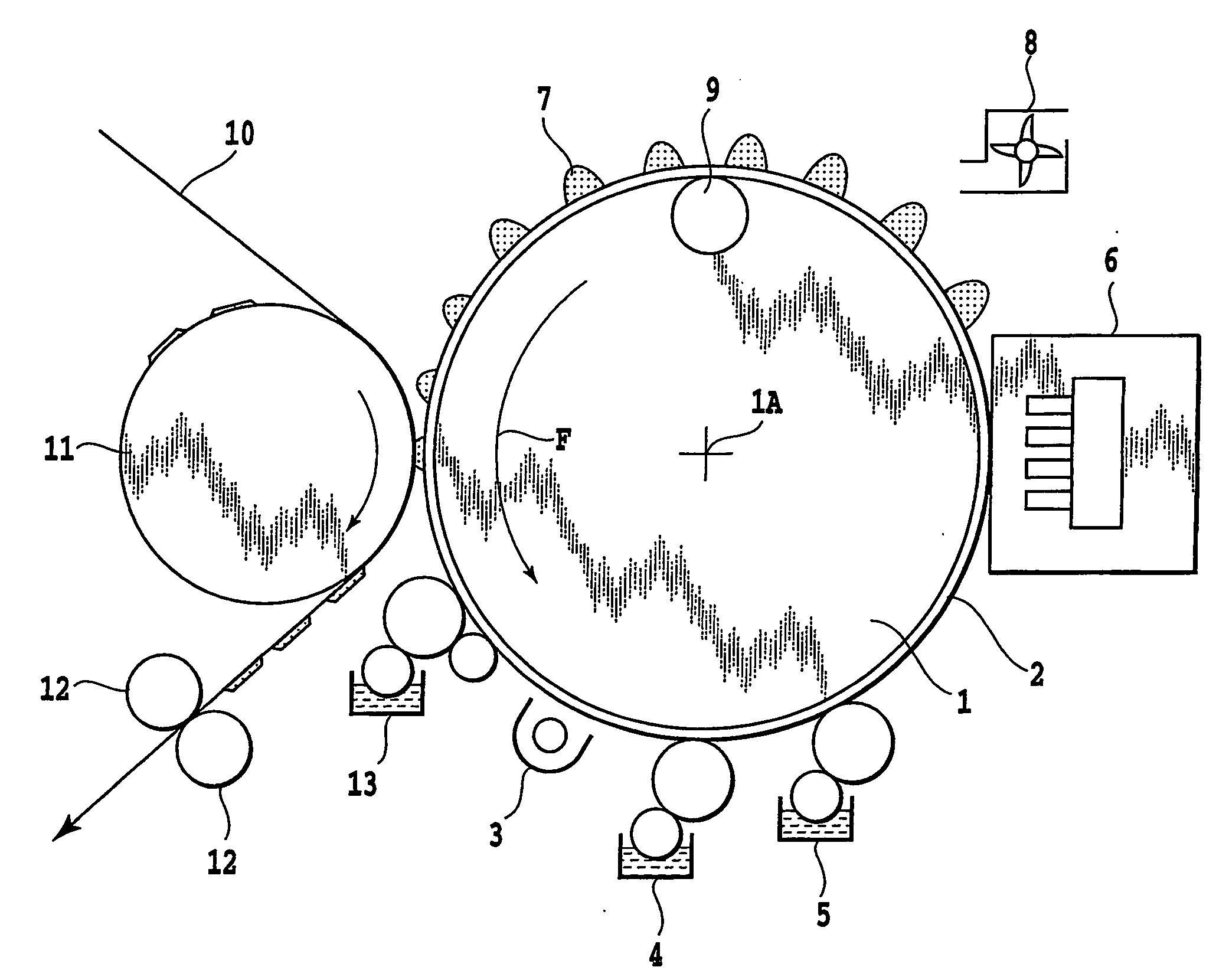
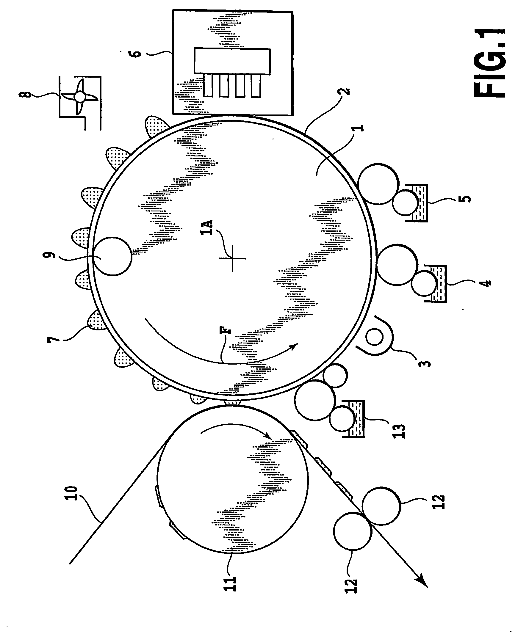
[0085]FIG. 1 is a schematic diagram showing an outline configuration of an image forming apparatus according to one embodiment of this invention. In FIG. 1, reference number 1 denotes an intermediate transfer body which is driven to rotate about an axis 1A in a direction of arrow F and has a surface layer 2 with good releasability. In FIG. 1, reference number 3 represents an energy application device that performs surface modifying processing on the surface layer 2. In the device shown in FIG. 1, application devices 4, 5 are put in contact with the surface of the intermediate transfer body 1 between the energy application device 3 and an ink jet printing unit 6 to apply a wettability improvement component and an ink viscosity increasing component to the surface. Although the application device 4 for applying a wettability improvement component such as surface active agent and the application device 5 for applying an ink v...

Example

[0150] 3. Example Embodiments

[0151] Next, some embodiments and examples for comparison will be explained in detail for each printing process. In the description that follows, “part” and “%” are expressed in mass terms unless otherwise specifically stated.

Example

Embodiment 1

[0152] (a) Surface Modification of Transfer Body

[0153] As an intermediate transfer body this embodiment used an aluminum drum coated with silicone rubber with a hardness of 40 degrees (KE12 of Shinetsu Kagaku make) to a thickness of 0.2 mm. First, the surface of the intermediate transfer body was modified under the following conditions by using an atmospheric pressure plasma processor 3 (ST-7000 of Keyence make).

[0154] Irradiation distance: 5 mm

[0155] Plasma mode: High

[0156] Processing rate: 100 mm / sec

[0157] (b) Application of Ink Viscosity Increasing Component

[0158] Next, the intermediate transfer body whose surface was modified was coated with an ink viscosity increasing component using a roll coater. As the ink viscosity increasing component, a 10% by mass aluminum chloride hexahydrate solution in water was used.

[0159] (c) Forming of Image on Intermediate Transfer Body

[0160] Next, the ink jet printing unit (nozzle density: 1200 dpi (dots / inch), ejection volum...


PUM

PropertyMeasurementUnit
Angleaaaaaaaaaa
Angleaaaaaaaaaa
Pressureaaaaaaaaaa

Abstract

The invention allows an image printing on a wide range of print media regardless of how much ink the print media absorb, without sacrificing a high printing flexibility of an ink jet printing system. To this end, the image forming method of this invention includes: a process of modifying a surface of an intermediate transfer body by applying energy to the surface; a process of ejecting ink onto the surface-modified intermediate transfer body by using an ink jet printing device; and a process of transferring ink from the intermediate transfer body to a print medium. With this invention, therefore, an ink image can be formed on the intermediate transfer body having a surface layer, without causing bleeding or beading, and then transferred onto the print medium in good condition.

Description

TECHNICAL FIELD [0001] The present invention relates to an image forming method and an image forming apparatus both using an ink jet printing system, an intermediate transfer body used in the image forming method and a method of modifying a surface of the intermediate transfer body. More particularly the present invention relates to an image forming method and an image forming apparatus, both of which use an intermediate transfer body in forming an image on a print medium in order to make it unlikely for an image quality to be affected by the amount of ink absorbed in the print medium, an intermediate transfer body used in the image forming method and a method of modifying a surface of the intermediate transfer body. BACKGROUND ART [0002] A mainstream image forming method using paper as print media is currently an offset printing. The offset printing is a technique suited for mass printing. That is, a printing plate for an image is fabricated and set in a printing machine to make co...

Claims


Application Information

Patent Timeline
IPC IPC(8): B41J2/01B41J2/005
CPCB41J2/0057B41M5/0011B41M5/0256B41M7/0027B41J2/005B41J2/01
Inventor TANIUCHI, HIROSHIMOURI, AKIHIRO
Owner CANON KK
Why Eureka
Try Eureka