Hybridization system using the control of pump and valves in closed system

a technology of closed system and hybridization system, which is applied in the field of hybridization system, can solve the problems of large amount of sample needed, serious contamination of hybridization chamber, and incompatibility of apparatus, so as to simplify the manufacturing process of micro flow channel or chamber, prevent contamination of micro flow channel and chamber, and facilitate separation and cleaning

Inactive Publication Date: 2006-07-13
SAMSUNG ELECTRONICS CO LTD
View PDF6 Cites 4 Cited by
  • Summary
  • Abstract
  • Description
  • Claims
  • Application Information

AI Technical Summary

Benefits of technology

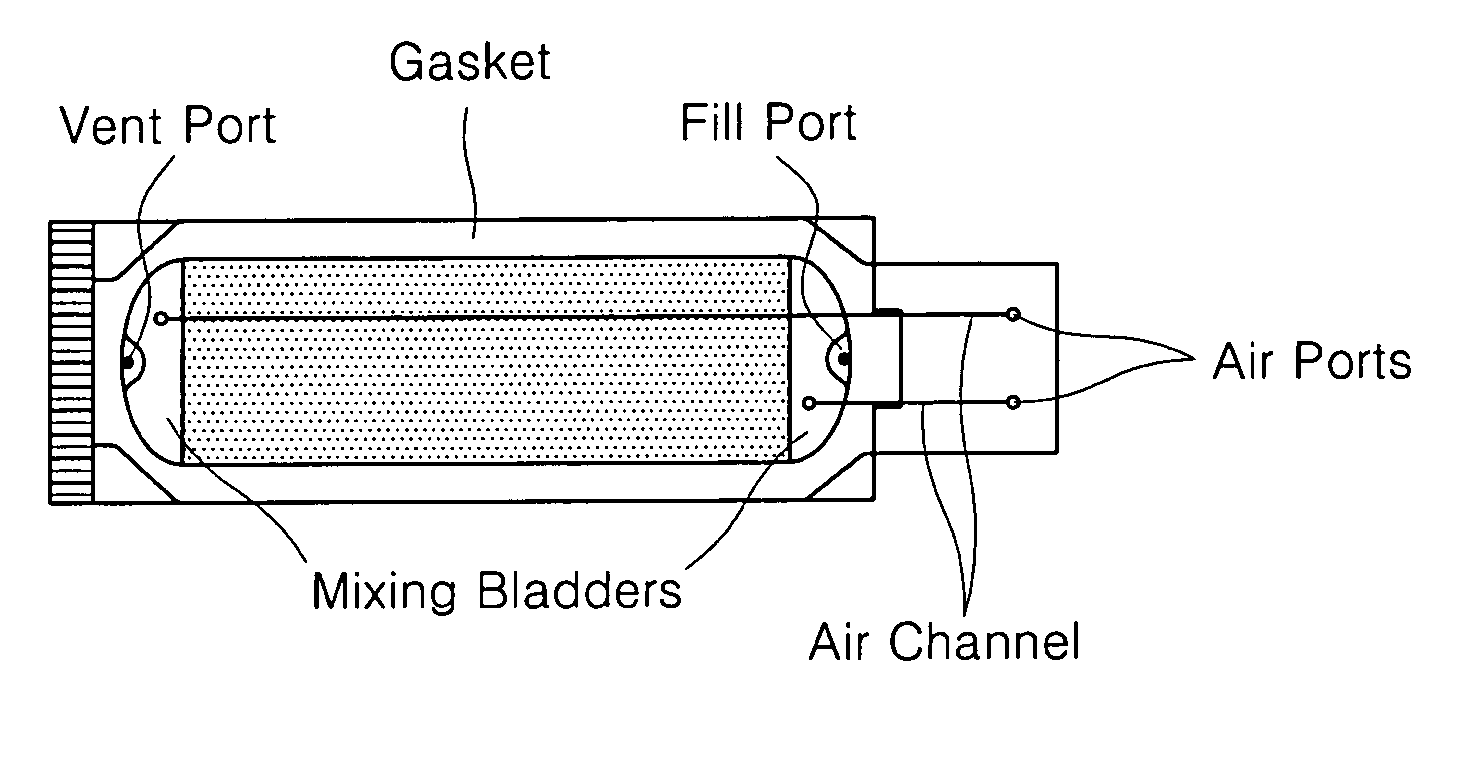
[0048] According to the present invention, only one of the upper substrate and the lower substrate has the protruding portion and the recessed portion. On the other hand, conventionally, each of the upper substrate and the lower substrate has the recessed portion, thus resulting in the requirement of a rubber O-ring. Therefore, according to the present invention, the manufacturing process for the micro flow channel or the chamber can be simplified, and the contamination of the micro flow channel and the chamber can be prevented. Further, the integration of the sealing element and the substrate contributes to ease of separation and cleaning.
[0049] The hybridization system is used to effectively diffuse a target solution to the chip. In order to effectively bind the target solution to the probe affixed on the chip, a micro pump alternatively pumps air in two directions and valves are controlled in a closed system.

Problems solved by technology

This results in variations in experimental conditions according to users, a long testing time of 16 to 17 hours, and the requirement of up to 100 μl or less of a sample.
However, for this apparatus, a large amount of the sample is needed due to the use of a peristaltic pump and a circulation fluid channel.
In addition, only the chip obtained from Affymetrix Co can be used in the cartridge, that is, this apparatus is incompatible.
For effective agitation in the chamber, the sample is mixed after filling a target solution up to a cover of the chamber so that the hybridization chamber is seriously contaminated.
In this case, however, a large amount of the sample, up to 220 μl, is needed because the sample must be circulated.
In this case, however, the hybridization system does not include an agitation device to diffuse the sample.

Method used


Image

  • Hybridization system using the control of pump and valves in closed system
  • Hybridization system using the control of pump and valves in closed system
  • Hybridization system using the control of pump and valves in closed system

Examples


example

Application of Hybridization system according to the present invention

[0090] A MODY3 chip hybridized using a hybridization system hybridization method was compared with a MODY3 chip hybridized using a conventional cover slide patch method. The probes indicated in Table 1 were used.

TABLE 1WPsequenceMPSequenceE02-01rwpgacttgaccatcTTCgccacacgE02-01rmpgacttgaccatcTCCgccacacgE02-05rwptcccgctgtGGGatgttgtgctgcE02-05rmptcccgctgtGTGatgttgtgctgcE02-08rwptggtatcgaccACCttcccgctgtE02-08rmptggtatcgaccATCtcccgctgtE02-10rwpttgggacaggTGGgactggttgagE02-10rmpttgggacaggTAGgactggttgag

[0091] First, the probes, which corresponds to a target nucleic acid MODY3, were affixed on a substrate, thus forming a microarray. In detail, a wild probe (WP) and a mutant probe (MP) were added to a solution mixture of polyethylenglycol (PEG), which has a molecular weight of 10,000, 0.025M (pH 10) of a sodium carbonate buffer, and formamide in a weight ratio of 1:1:2. The resulting solution was spotted on a silicon waf...


PUM

PropertyMeasurementUnit
temperatureaaaaaaaaaa
heightaaaaaaaaaa
heightaaaaaaaaaa

Abstract

Provided is a hybridization system for hybridizing a biochip including: a chamber device including at least a hybridization chamber including a support for a biochip and a first cover having a sample inlet; an agitation device including: two air channels connected to ends of the hybridization chamber; two valves disposed in the air channels; an integrated air channel to which the two air channels are connected; and an air pump disposed in the integrated air channel; and a washing and drying device including: a flow channel connected to one of the two air channels through a branched valve; a flow pump disposed in the flow channel; and a buffer inlet disposed opposite the flow channel.

Description

CROSS-REFERENCE TO RELATED PATENT APPLICATIONS [0001] This application claims the benefit of Korean Patent Application No. 10-2004-0101654, filed on Dec. 6, 2004, in the Korean Intellectual Property Office, the disclosure of which is incorporated herein in its entirety by reference. BACKGROUND OF THE INVENTION [0002] 1. Field of the Invention [0003] The present invention relates to a hybridization system, and more particularly, to a hybridization system in which operations for hybridization of a biochip, such as sample diffusing, sample agitating, chip washing, and chip drying are automized. [0004] 2. Description of the Related Art [0005] A biochip is formed by affixing on a support a bimolecular probe to be analyzed with high density. The biomolecular probe may be DNA, protein, or the like. By detecting whether the probe is hybridized with a target material contained in a sample, gene expression characteristics, genetic defects, protein distribution, reaction characteristics, or th...

Claims


Application Information

Patent Timeline
Patent Type & Authority Applications(United States)
IPC IPC(8): C12M1/34B01F33/40
CPCB01F13/0059B01F13/0222B01L3/5027B01L7/00B01L2200/0689B01L2300/0636B01L2300/14B01L2300/1822B01L2400/0487G01N2035/00544B01F33/30B01F33/403C12M25/06C12M27/04C12M41/12
Inventor LEE, SOO-SUKJUNG, SUNG-OUKYOO, CHANG-EUNLEE, HUN-JOOKO, CHRISTOPHER HANSUNGHUH, NAM
Owner SAMSUNG ELECTRONICS CO LTD
Why Eureka
Try Eureka