
Method and a tool for allocating computational resources in a distributed control system

a distributed control system and computational resource technology, applied in the field of process control, monitoring and automation systems, can solve the problems of complex control system setup and configuration, difficult task of optimal distribution of complete control function to the various components of process control system, and the inability to provide more than limited information to the controller

Inactive Publication Date: 2006-07-13
ABB RES LTD
View PDF11 Cites 6 Cited by
  • Summary
  • Abstract
  • Description
  • Claims
  • Application Information

AI Technical Summary

Benefits of technology

[0025] The principle advantage of the invention is that a control engineer may design and configure the complete control function of a process control system without taking into consideration the underlying process control system hardware structure and its technical characteristics regarding memory and communication, because the method of the invention automatically designs an optimal hardware structure and distributes the control functions that make up the complete control function onto the optimal hardware structure, ensuring that the requirements are met or, if they cannot be met due to limitations, this is notified to the control engineer, which can either change the hardware structure and its components or change the control functions or relax the requirements. Thus, design and distribution of the control function can be largely decoupled from the actual hardware structure.
[0026] In the context of process control, monitoring and automation systems for industrial and manufacturing plants, the invention is particularly concerned with the methods carried out at the engineering station(s). The engineering process that begins with the definition of the plant and plant areas, includes the definition and design of control strategies, the definition and design of the HW / SW architecture, and the design and distribution of the executable control code that runs in the:
[0031] A basis of this invention comprises process control systems with distributed computational resources and the task is to design a system with an HW / SW configuration that allows different SW configurations in the different HW capabilities of the system itself. As soon as a fault occurs in a HW component of the system, the tool reconfigures the whole system and the application software is shared in different HW components to recover the performance of the system.
[0032] The method and tool of the invention comprise three main parts that each can be used separate or combined with one of the other parts in a system comprising other solutions for solving the remaining steps of designing or configuring a process control system. The main parts are a method and a tool for designing an optimal hardware structure for a given control function, a method and a tool for automatically distributing the given control function onto a given hardware structure in an optimal way and a method and a tool for automatically implementing the functions and parameters for a given hardware structure a control function distribution.

Problems solved by technology

These devices typically provide only limited information to a controller, restricted mainly to analogue signals related to the readings or measurements made by these devices.
Setting up and configuring a control system that includes both traditional field devices and smart devices is a complex challenge.
Therefore, the optimal distribution of the complete control function to the various components of a process control system is a difficult task and becomes even more difficult with the above listed tendencies regarding an increasing number of components with controller-capability.
On the other hand, the state-of-the-art workflow has the disadvantage that the design of the control functions is not independent of the hardware system design.
The distribution of the control functions to the process control system hardware structure as well as a possible later re-distribution of the control functions to a new process control system hardware structure in case of failure of a component is a difficult task that is not resolved in the prior art.

Method used


Image

  • Method and a tool for allocating computational resources in a distributed control system
  • Method and a tool for allocating computational resources in a distributed control system

Examples


Embodiment Construction

[0036] While the design and configuration method and the tool therefore of this invention are described in detail in conjunction with a heterogeneous process control system containing certain hardware and software components including traditional field devices and smart field devices, it should be noted that the invention is not limited to such specific set of HW or SW components and that each part of the method and tool can be used together with other solutions for solving the remaining parts.

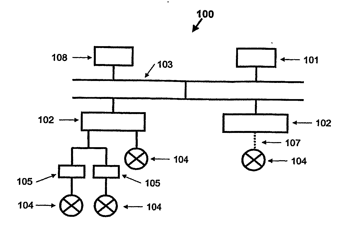
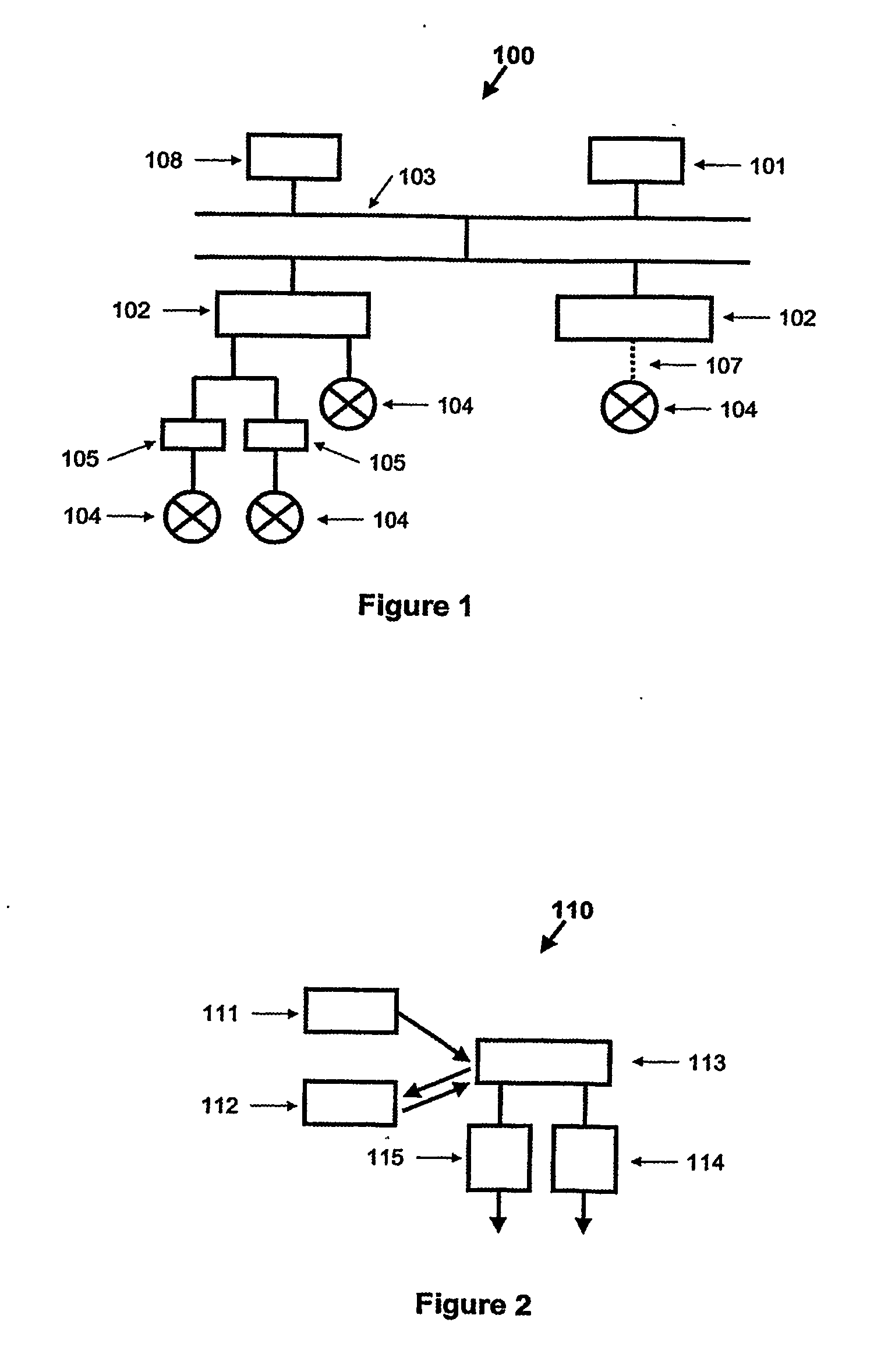
[0037]FIG. 1 shows a the hardware structure of a process control system 100 in which an operator station 101 is connected to distributed process controllers 102 via a digital network 103. The process controllers 102 are communicating with a number of field devices 104 that may include processing capability or remote I / O 105 via a digital control network 106 or via a wireless connection 107. An engineering station 108 provides the management of the heterogeneous process control system. The inv...


PUM


Abstract

The invention concerns method and a tool for designing an optimal hardware structure of a process control system and configuring a given control function onto the optimal hardware structure of the process control system. The method and the tool of the invention comprises three main parts that can be used in conjunction or be used separately together with other solutions for the remaining part or parts of the system.

Description

TECHNICAL FIELD [0001] The invention relates to process control, monitoring and automation systems for industrial and manufacturing plants. In particular it refers to tools and methods for enabling and facilitating the designing and configuration of process control systems. BACKGROUND ART [0002] A process control system is normally composed by several components with different scope. As an example we can consider a process control system to comprise one or more: [0003] operator stations to allow the operator to interact with the controlled process (e.g. to monitor the process and to activate actions on the process); [0004] engineering stations to allow the process engineer to configure the process control system off-line or on-line; [0005] controllers. Controllers are microprocessor-based components that acquire digital or analogue data from the process, and / or from the operator station, and generate outputs to the process or to the operator station. Controllers are normally program...

Claims


Application Information

Patent Timeline
IPC IPC(8): G05B11/01G05B19/42G05B15/02G05B19/042H04L25/02H04L25/03H04L27/26
CPCG05B15/02G05B19/042G05B2219/23293G05B2219/23424G05B2219/25428Y02P90/02
Inventor FAY, ALEXANDERLORITO, FABRIZIOPORETTA, STEFANOVAHLDIECK, ROLFWENDT, PETER
Owner ABB RES LTD
Learn More