Method and apparatus for providing signal analysis of a bionems resonator or transducer

a bionems resonator and transducer technology, applied in chemical methods analysis, instruments, digital computer details, etc., can solve the problems of inability to detect resonance, inconvenient application, and difficulty in harvesting potential, so as to reduce the size and nature of the instrumentation needed, reduce the noise of cantilever motion, and reduce the size of the cantilever.

Inactive Publication Date: 2006-07-13
CALIFORNIA INST OF TECH
View PDF7 Cites 12 Cited by
  • Summary
  • Abstract
  • Description
  • Claims
  • Application Information

AI Technical Summary

Benefits of technology

[0018] Moving down to the small size of NEMS devices offers several significant advantages. As already mentioned the small size of the NEMS devices permit them to be dramatically more responsive to the kinetics of binding and unbinding. This high frequency response is critical to following the stochastic nature of receptor ligand interaction, most receptor-ligand pairs interact dynamically, binding, remaining engaged for times ranging from microseconds to seconds (depending on the exact receptor-ligand pair), and then releasing. High frequency response (˜MHz) is critical if an assay is to follow biomolecular interactions. The ability to resolve the opening and closing of individual membrane channels in the patch-clamp (gigaohm seal) technology has revolutionized our understanding of the physical biochemistry underlying neuronal function; before the patch-clamp, experimenters could only attempt to decode molecular mechanism from recordings of huge populations of membrane channels. It is our belief that the analysis of biomolecules is presently in exactly the same state, limited by both the vast quantities of materials required and the smearing in time inherent in even the most sensitive assays. BioNEMS are thus poised by the invention to truly move our analysis of biomolecules to the stochastic limit.
[0019] One of the powers of this approach is that it exploits the thermal motion of the cantilever, normally a major limitation in AFM, as a driving force. Furthermore, the noise of cantilever motion becomes smaller as cantilever size is decreased. In addition, the small size of NEMS devices permits an array of detectors (≧500 cantilevers) to be constructed in a small active volume (≦1100 pL). This latter advantage is of great significance, as it offers the promise of a technology for sensing the levels of RNA, proteins and second messengers present in single cells.
[0020] The BioNEMS approach of the invention offers a major reduction in the size and nature of the instrumentation needed for it to operate (in comparison to AFM / CFM). The sensor for the motion of the cantilever will be integral to the NEMS cantilever, which eliminates the size and density limits that would be imposed by the optical detection of cantilever motion used in AFM. This will permit the BioNEMS cantilevers to be much smaller and to be dramatically more closely packed than is practical in AFM.

Problems solved by technology

These watershed experiments show the feasibility of measuring chemical events at the stochastic limit, but also offered evidence of the difficulty of harvesting this potential in a small, portable and robust device.
The fluid will damp the NEMS cantilever making resonance detection impossible, and the thermal energy of the solution will buffet the cantilever.
Although these approaches are becoming increasingly widespread, the large size of the reader instrumentation and the intrinsic limitations of the fluorescence analysis employed make them completely inappropriate for applications in which both portability and robust performance are required.
Furthermore, they are single-use devices, hence they cannot easily accommodate applications that require continuous monitoring.
Finally, the devices rely on significant volumes of analyte, making them ill-suited to the most powerful recent advances in drug discovery provided by combinatorial chemistry or to the most sensitive assays of gene expression.
The range of these forces are well within the capability of AFM instrumentation to detect; however, an AFM cantilever in solution does not have the temporal response characteristics needed to permit the binding and unbinding of biological ligands and their receptors to be followed reliably.

Method used


Image

  • Method and apparatus for providing signal analysis of a bionems resonator or transducer
  • Method and apparatus for providing signal analysis of a bionems resonator or transducer
  • Method and apparatus for providing signal analysis of a bionems resonator or transducer

Examples


Embodiment Construction

Physical Parameters that Govern SNR in Stochastic Signal Detection in BioNEMS Devices

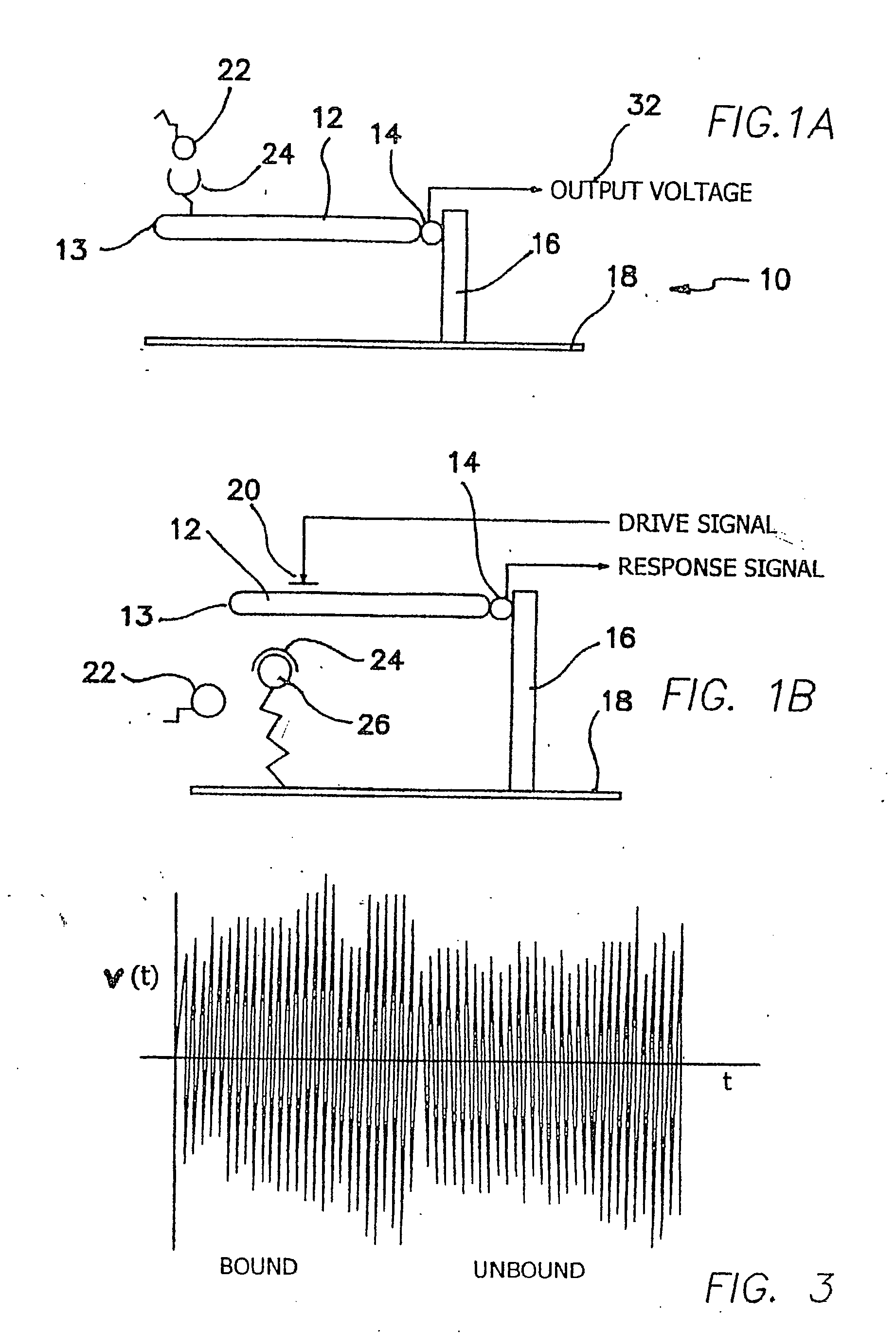
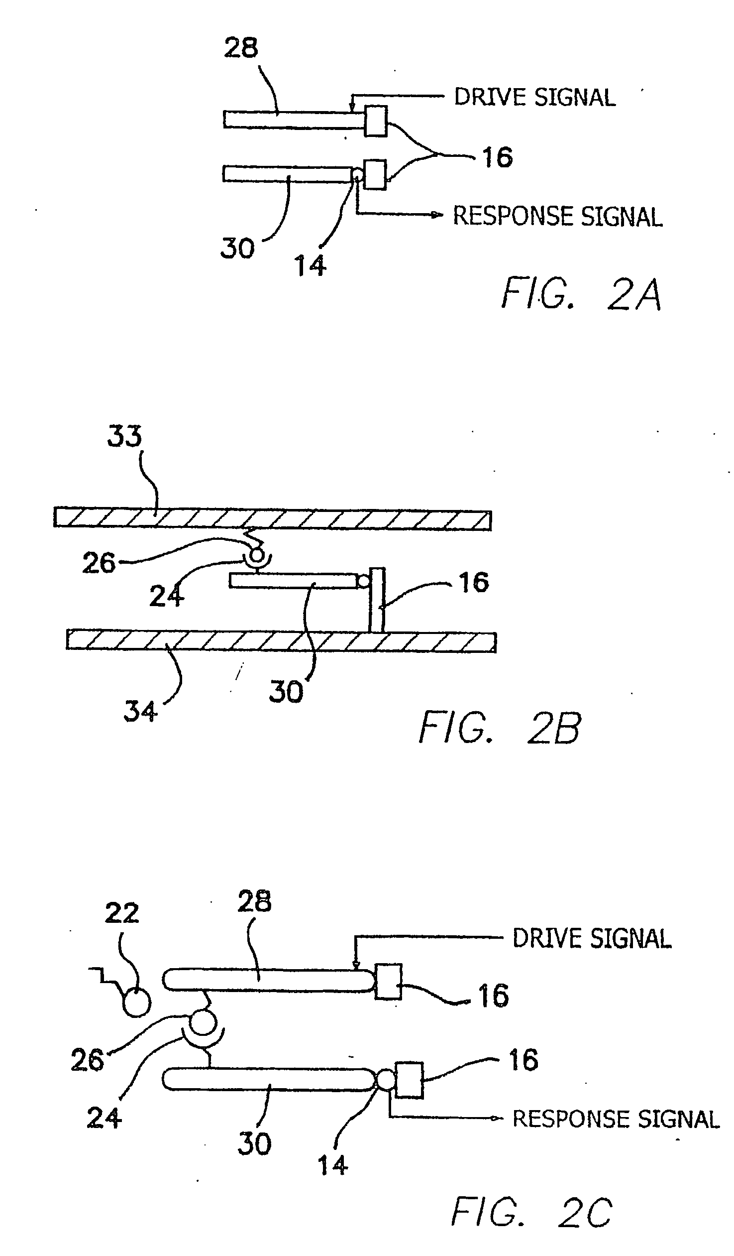
[0056] The illustrated embodiments disclose several signal detection strategies for several NEMS device configurations. Four embodiments are illustrated, the second of which is a simple variation of the first, which are shown in FIGS. 1a, 1b, 2a, and 2b. FIG. 1a shows a passive one-port device 10, while FIG. 1b shows the same embodiment using in an active mode, i.e. in which an external drive signal is applied to vibrate the cantilever. A submicron or NEMS cantilever beam 12 in FIG. 1a is coupled via a NEMS output device 14 to a support 16 mounted in turn on a substrate 18. Free ligand molecules 22 are available for binding to bound receptor molecules 24 on beam 12. In FIG. 1b a gate drive 20 is coupled to beam 12 and there is also bound ligands 26 on substrate 18 combined or combinable with receptors 24 on beam 12. Bound ligands 26 are identical to free ligands 22 except for being complexed with ...


PUM

PropertyMeasurementUnit
sizeaaaaaaaaaa
forcesaaaaaaaaaa
forcesaaaaaaaaaa

Abstract

An outputs signal, v(t), is generated from a bioNEMs transducer and mixed with a reference signal and then filtered to generate a correlator output, r(t). The correlator output is detected to generate a signal u(t) and then determined whether the signal u(t) satisfies a predetermined threshold. If qualified, it is then decided whether the signal u(t) represents a predetermined type of interaction between a free ligand in a fluid in which the NEMS device is immersed and a receptor attached to the transducer. The threshold is the Neyman-Pearson criterion based on a predetermined probability of false detection, Pfa. The interaction may be binding of a free ligand to the receptor or releasing a bound ligand from the receptor by competitive binding with the free ligand. The step of detecting comprises detecting the envelope of the signal, r(t).

Description

RELATED APPLICATIONS [0001] The present application is related to U.S. Provisional Patent Applications Ser. No. 60 / 379,507, filed on May 7, 2002; Ser. No. 60 / 379,712, filed on May 7, 2002; Ser. No. 60 / 379,618, filed on May 7, 2002; and Ser. No. 60 / 379,555, filed on May 7, 2002, which are incorporated herein by reference and to which priority is claimed pursuant to 35 USC 119. INCORPORATION OF COPENDING APPLICATIONS [0002] It is to be expressly understood that the present application incorporates by reference simultaneously filed applications serial no. (PAU.34), entitled, “An Apparatus And Method For Vacuum-Based Nanomechanical Energy, Force, And Mass Sensors”; and serial no. (PAU.36), entitled “Dynamics Bionems Sensors And Arrays Of BIONEMS Sensor Immersed In Fluids” as if set out in their entirety. Further, the present application incorporates by reference U.S. patent application Ser. No. 10 / 138,538, filed on May 3, 2002 entitled, “An Apparatus and Method for Ultrasensitive Nanoel...

Claims


Application Information

Patent Timeline
Patent Type & Authority Applications(United States)
IPC IPC(8): G01N33/48G01N33/543
CPCG01N33/54373
Inventor ROUKES, MICHAEL L.FRASER, SCOTT E.SOLOMON, JERRY E.
Owner CALIFORNIA INST OF TECH
Why Eureka
Try Eureka