
Multiple degree of freedom micro electro-mechanical system positioner and actuator

a micro electromechanical and actuator technology, applied in mechanical devices, generators/motors, machines/engines, etc., can solve the problems of more than 1 db loss, actuation, and not being able to meet the planar structure typical of semiconductor fabrication and mems devices

Inactive Publication Date: 2006-07-20
MASSACHUSETTS INST OF TECH
View PDF19 Cites 7 Cited by
  • Summary
  • Abstract
  • Description
  • Claims
  • Application Information

AI Technical Summary

Benefits of technology

[0009] One aspect of the present invention includes a micro electro-mechanical system (MEMS) positioner which includes a stage within a first layer of semiconductor material. The first layer also includes a series of beams, a series of first flexure hinges coupled to the stage and to the beams, and a plurality of first controlled input thermal actuators extending longitudinally therein. The first actuators are coupled to the first beams at spaced locations thereon. A second stage extends in a planar direction within a second layer of semiconductor material. The second layer also includes a series of second beams, a series of second flexure hinges coupled to the second stage and to the second beams, and a series of second controlled input thermal actuators extending longitudinally therein. The second actuators are coupled to the second beams at spaced locations thereon. T

Problems solved by technology

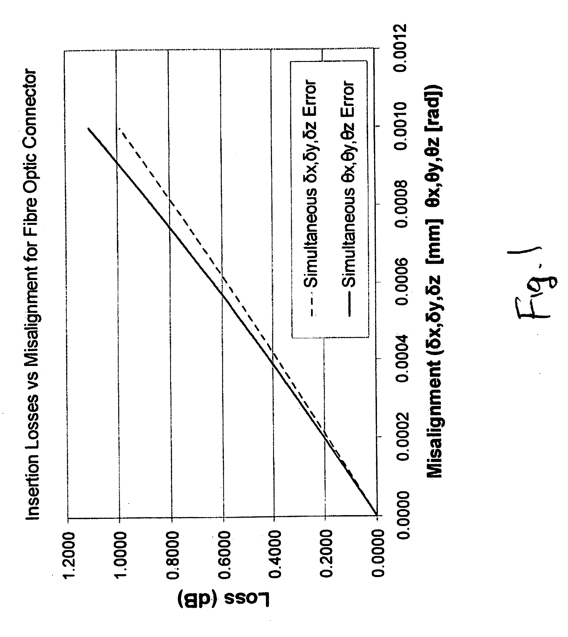
Likewise, angular misalignment as small as 0.001 rad (0.057 degree) may result in more than 1 dB loss.
Unfortunately, conventional alignment devices typically require actuation along at least three mutually orthogonal axes in order to generate movement with six degrees of freedom.
Such actuation, however, does not lend itself to the planar structures typically associated with semiconductor fabrication and MEMS devices.

Method used


Image

  • Multiple degree of freedom micro electro-mechanical system positioner and actuator
  • Multiple degree of freedom micro electro-mechanical system positioner and actuator
  • Multiple degree of freedom micro electro-mechanical system positioner and actuator

Examples


example

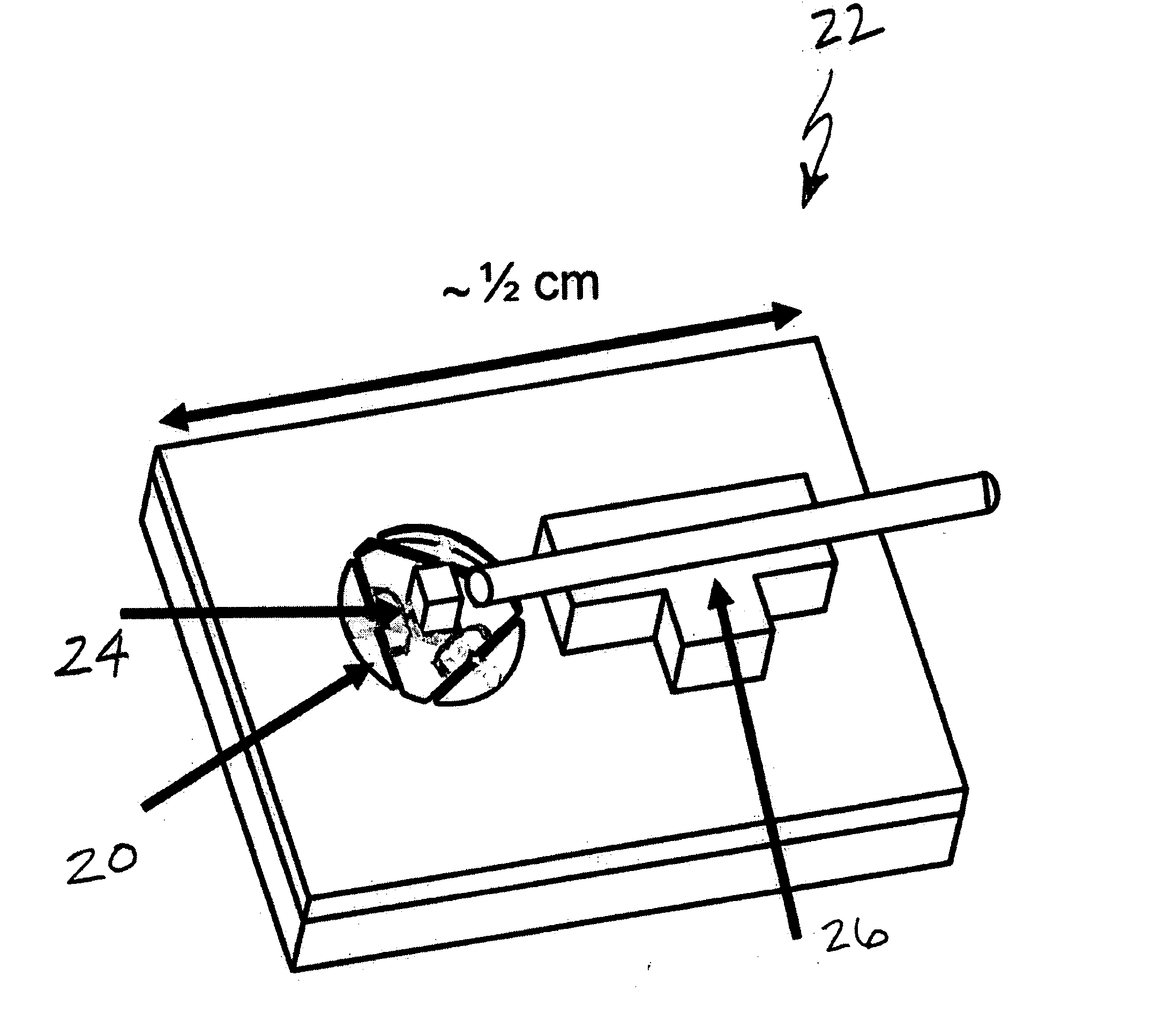
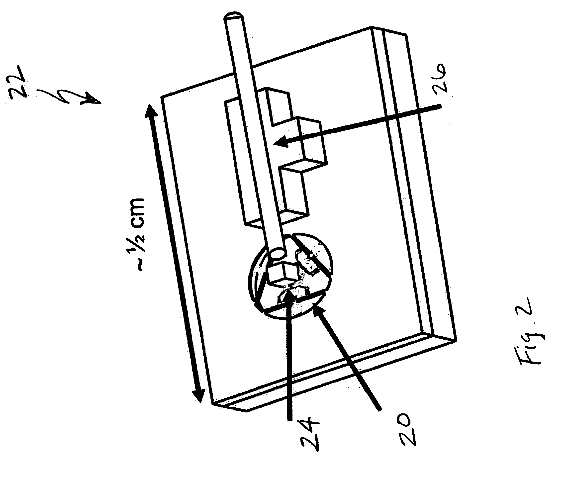
[0060] An exemplary device 20 of 3 mm in diameter was fabricated substantially and shown and described with respect to FIG. 11. A double SOI wafer with two device layers of thickness 8 μm, and two oxide layers 1 μm (N type / Sb Doped / / Resistivity=0.01˜0.1 ohm / cm) was used in step 60. An Endura™ vapor deposition machine was used to sputter a 5000 Angstroms aluminum (Al+2% Si) metallization layer in step 66. A vapor of concentrated HF (49%) was used to etch oxide layer 82′ in step 76.

[0061] In-plane and out-of-plane tests were conducted on the resulting device 20 using a ZYGO™ white light interferometer and a Micro-vision™ system to view the static and dynamic functions. Displacement of the device was measured and plotted as a function of input current as shown in FIGS. 12A and 12B. These test results indicated actual, non-calibrated displacement generally within 10 percent of theoretical, using finite element analysis (FEA). The working temperature is expected to be within the range o...


PUM


Abstract

A micro electro-mechanical system (MEMS) positioner, including an actuator and method for making the same, includes a stage formed within a first layer of semiconductor material, along with a series of beams, flexure hinges and controlled input thermal actuators. The actuators are operatively engaged with a second layer, and are selectively actuatable to effect longitudinal expansion thereof, so that relative actuation between individual ones of actuators spaced in the planar direction relative to one another is configured to generate controlled movement of the stage within the planar direction, and relative actuation between individual ones of actuators spaced orthogonally to the planar direction relative to one another is configured to generate controlled movement of the stage out of the planar direction. The relative position between the stage and the support is adjustable in each of six degrees of freedom, so that the compliant mechanism forms a quasi-static precision manipulator.

Description

[0001] This application is related to U.S. patent application Ser. No. 10 / 175,415, filed on Jun. 19, 2002, entitled “Six Degree of Freedom Flexure Stage”.BACKGROUND OF THE INVENTION [0002] (1) Field of the Invention [0003] The present invention relates generally to a MEMS (Micro Electro-Mechanical Systems) device, and more particularly, to a micro-scale alignment device capable of repeatedly aligning a stage portion relative to a support structure with a relatively high degree of accuracy and precision with up to six degrees of freedom. [0004] (2) Background Information [0005] There is a growing need for fine motion control and positioning at micro and nano scales, such as for the growing number of MEMS applications, including active alignment of fiber optic elements, x-y stages with nanometer level resolution, and machine elements for micro-scale machinery. Also, micro-mirrors, micro-resonators, and manipulation for bio molecules . . . etc will require multi-axis nano and micro-pos...

Claims


Application Information

Patent Timeline
IPC IPC(8): H02N10/00F02G1/04F01B29/10
CPCF03G7/00H02K2201/18H02N10/00F03G7/06
Inventor CULPEPPER, MARTIN L.CHEN, SHIH-CHI
Owner MASSACHUSETTS INST OF TECH
Learn More