Hydraulic valve driving device and engine including the same and vehicle

Inactive Publication Date: 2006-07-20
YAMAHA MOTOR CO LTD
View PDF4 Cites 34 Cited by
  • Summary
  • Abstract
  • Description
  • Claims
  • Application Information

AI Technical Summary

Benefits of technology

[0009] In order to overcome the problems described above, preferred embodiments of the present invention provide a hydraulic valve driving device that allows quick

Problems solved by technology

In the hydraulic valve driving device that drives the hydraulic pump by the crank, however, the hydraulic pump is driven together with the engine itself whose inertia is large, and therefore the rotation speed of the hydraulic pump is not quickly raised.
Therefore, it takes long for the oil pressure to be raised, and therefore it takes long before the engine valve is driven stably.
This makes it difficult to

Method used


Image

  • Hydraulic valve driving device and engine including the same and vehicle
  • Hydraulic valve driving device and engine including the same and vehicle
  • Hydraulic valve driving device and engine including the same and vehicle

Examples


Embodiment Construction

[0085] Now, preferred embodiments of the invention will be described with reference to the accompanying drawings. In the following preferred embodiments, a motorcycle will be described as an example of a vehicle according to the invention.

(1) First Preferred Embodiment

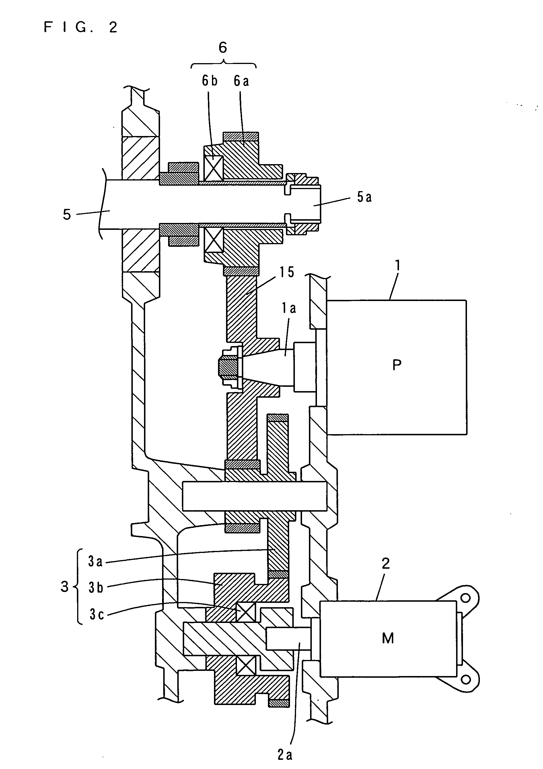
[0086] Now, with reference to FIGS. 1 to 4, an engine including a hydraulic valve driving device according to a first preferred embodiment of the invention will be described.

(1-1) Structure of Engine

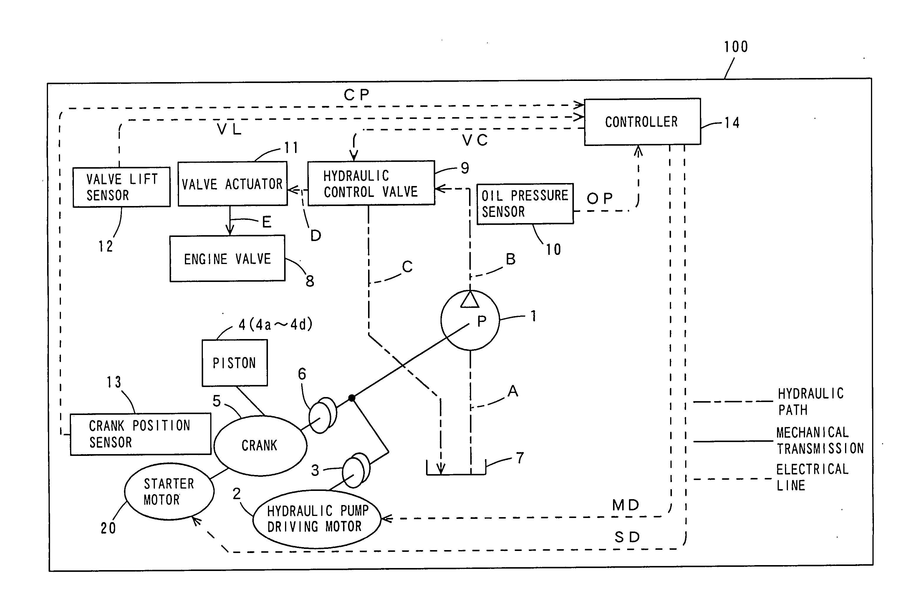
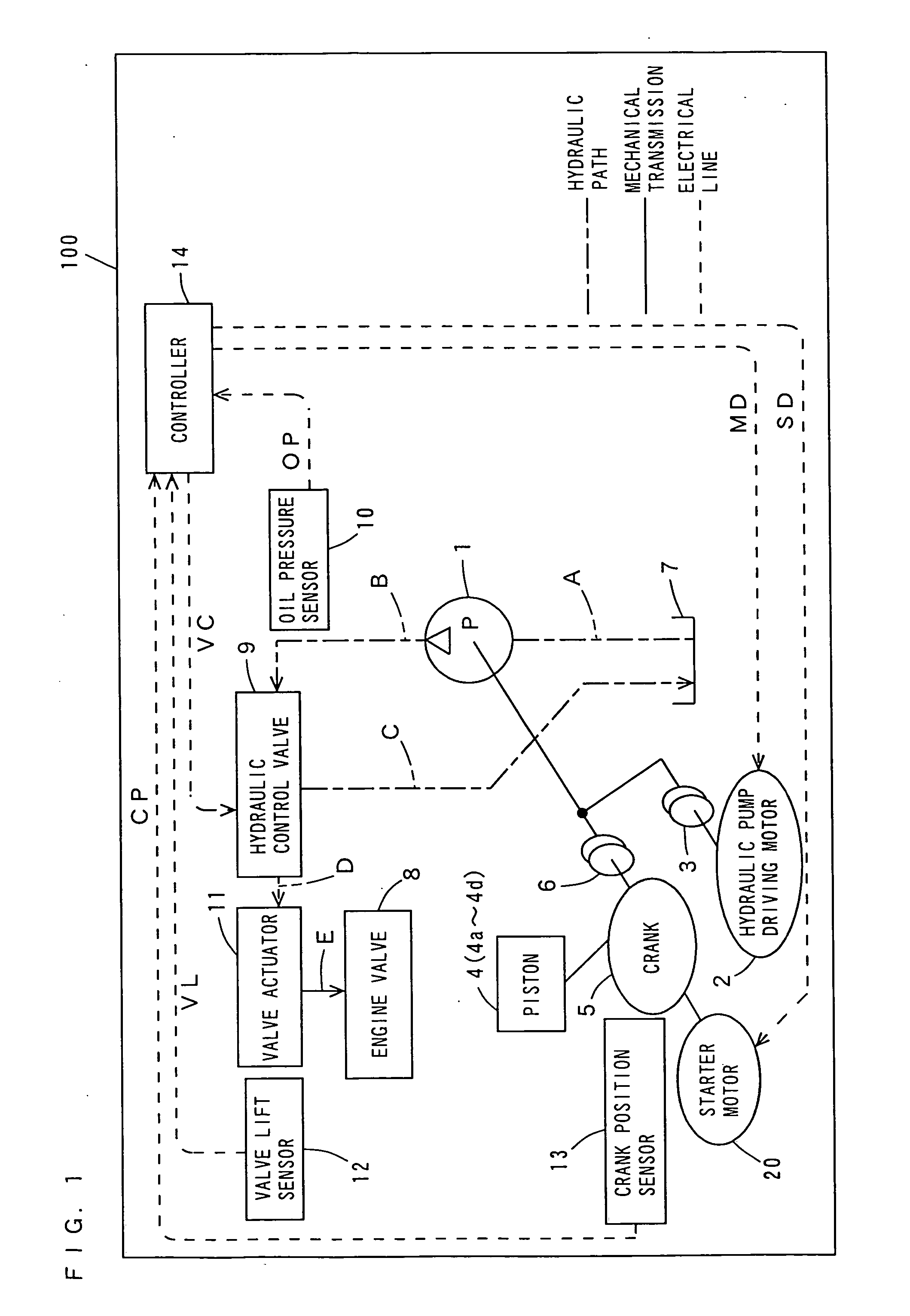
[0087]FIG. 1 is a schematic view of a general structure of a hydraulic valve driving device in an engine according to the first preferred embodiment of the invention.

[0088] As shown in FIG. 1, the hydraulic valve driving device in the engine 100 according to the first preferred embodiment includes a hydraulic pump 1, a hydraulic pump driving motor 2, transmission switching mechanisms 3 and 6, an oil tank 7, an engine valve 8, a hydraulic control valve 9, an oil pressure sensor 10, a valve actuator 11, a valve lift sens...


PUM


Abstract

A hydraulic valve driving device includes a valve actuator operable to drive an engine valve, a hydraulic pump that generates the oil pressure for the valve actuator, a hydraulic pump driving motor that drives the hydraulic pump, and a starter motor. At the time of engine starting, after the hydraulic pump is driven by the hydraulic pump driving motor while the crank is stopped in the first engine-starting mode, and then the crank and the hydraulic pump are driven by the starter motor in the second engine-starting mode.

Description

BACKGROUND OF THE INVENTION [0001] 1. Field of the Invention [0002] The present invention relates to a hydraulic valve driving device that drives an engine valve using hydraulic pressure and an engine including the hydraulic valve driving device and a vehicle including the engine. [0003] 2. Description of the Background Art [0004] There have been conventionally known hydraulic valve driving devices that drive an engine valve including an intake valve and an exhaust valve using oil pressure (see, for example, JP 5-202710 A). [0005] Such a hydraulic valve driving device is provided with a hydraulic pump operable to generate oil pressure. In the hydraulic valve driving device disclosed by JP 5-202710 A, at the time of engine starting, the intake valve and the exhaust valve are prevented from operating before the oil pressure in the hydraulic pump reaches a prescribed value or higher, so that the intake valve and the exhaust valve are allowed to operate in a stable manner. [0006] In the...

Claims


Application Information

Patent Timeline
IPC IPC(8): F01L9/02F01L1/34F01L9/10
CPCF01L9/02F01L2800/01Y10T477/656F01L2820/045F01L2820/042F01L9/10F02N19/004F02N11/00F02N15/043F02N15/023
Inventor MORIWAKI, YUJITSUCHIDA, NAOKI
Owner YAMAHA MOTOR CO LTD
Why Eureka
Try Eureka