
Electron beam tube output arrangement

Active Publication Date: 2006-07-20
E2V TECH (UK) LTD
View PDF3 Cites 0 Cited by
  • Summary
  • Abstract
  • Description
  • Claims
  • Application Information

AI Technical Summary

Benefits of technology

[0014] The embodiment of the invention enables the amplified RF signal transmitted from a travelling wave tube (TWT) to be divided, from a single output signal into two or more output signals. Each of the transmitted outputs being of the same frequency and equivalent power levels. The divider forms an integral part of the TWTs RF output section and as such is capable of transmitting high power RF signals over a broad bandwidth. The size and mass of the divider are minimised by incorporating the divider inside the vacuum envelope of the TWT. This makes the TWT / divider combination suitable for airborne applications where stringent conditions are encountered. Such conditions include wide temperature ranges (e.g. from −55° C. to >200° C.) and high altitude (70 Kft).

Problems solved by technology

Both of these systems are inherently higher mass and volume, with consequential cost implications.

Method used


Image

  • Electron beam tube output arrangement
  • Electron beam tube output arrangement
  • Electron beam tube output arrangement

Examples


Embodiment Construction

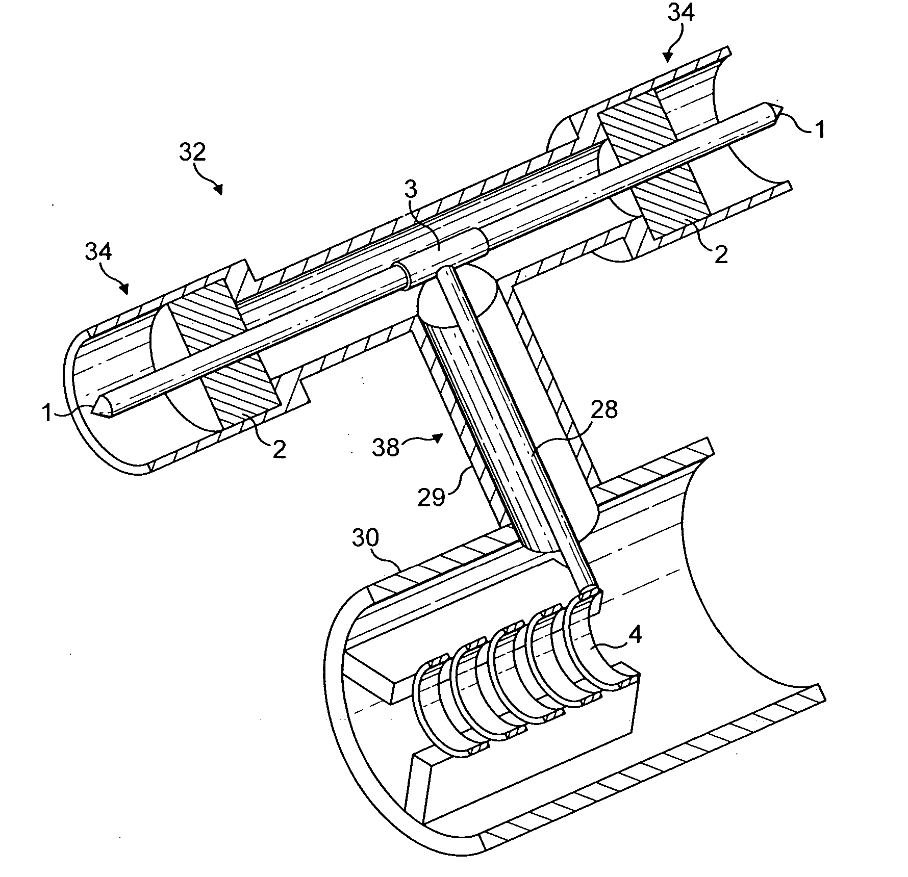
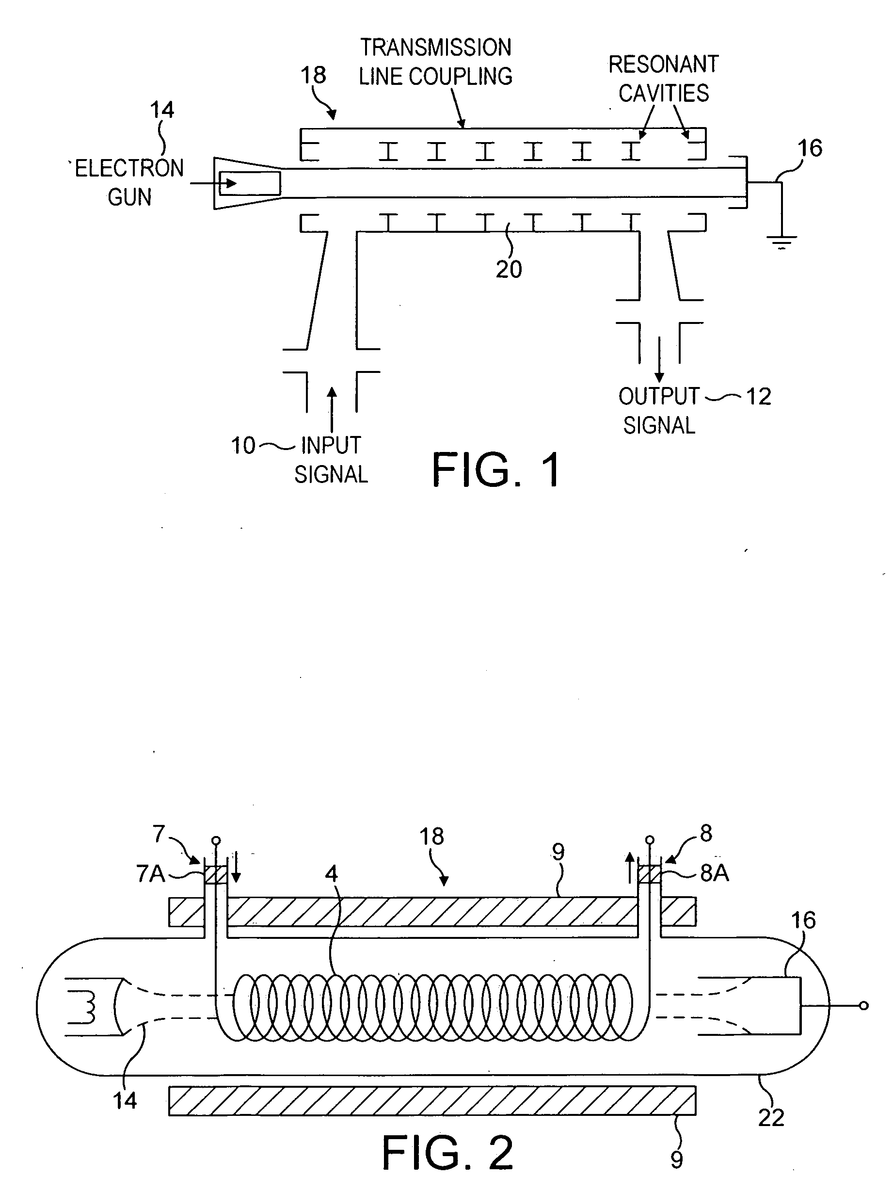
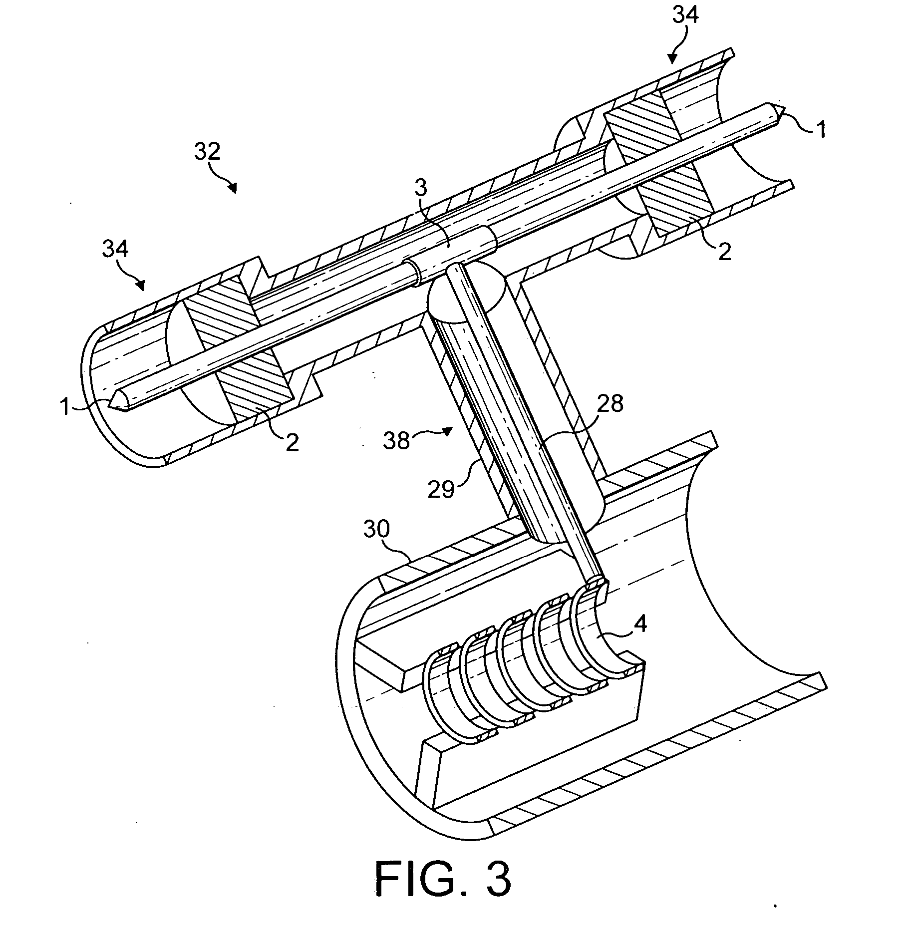
[0019] The embodiment described in a helix type travelling wave tube (TWT) but the invention may be applied to other electron beam devices such as those described above. The main components of a known helix type TWT have already been described and are briefly repeated for ease of reference with respect to the schematic arrangement of FIG. 2 which may be altered to embody the invention as shown in FIG. 3.

[0020] The TWT comprises an electron gun 14, an RF interaction circuit 18 in the form of a helix 4 and a collector 16. An input coaxial line 7 provides an RF input and an output coaxial line 8 takes the RF output. Seals 7A, 8A at the input and output close the vacuum shown schematically as an envelope 22.

[0021] The TWT embodying the invention has a modified output arrangement shown in FIG. 3. A portion of the helix 4 in the RF interaction circuit is shown and connects to the central conductor 28 of an output coaxial line 38 in known fashion. The outer housing 30 of the TWT tube con...


PUM


Abstract

An electron beam tube of the type for amplification of RF signals comprising an electron gun, an interaction region within a vacuum, an RF input and an RF output arrangement, the RF output arrangement comprising an output coaxial line and a coaxial divider, wherein the coaxial divider is arranged to divide a signal on the coaxial line into a plurality of signals and wherein the vacuum within the interaction region extends into the coaxial divider.

Description

CROSS-REFERENCE TO RELATED APPLICATION [0001] This application claims the priority of British Application No. 0428379.2, filed on Dec. 24, 2004, the subject matter of which is incorporated herein by reference. BACKGROUND OF THE INVENTION [0002] This present invention relates to an output arrangement for electron beam tubes, and to a travelling wave tube incorporating an output arrangement. [0003] Electron beam tubes are used for the amplification of RF signals and are typically linear beam devices. There are various types of linear electron beam tube known to those skilled in the art, examples of which include the Travelling Wave Tube (TWT), the klystron and the Inductive Output Tube (IOT). Linear electron beam tubes incorporate an electron gun for the generation of an electron beam of an appropriate power. The electron gun includes a cathode heated to a high temperature so that the application of an electric field between the cathode and an anode results in the emission of electron...

Claims


Application Information

Patent Timeline
IPC IPC(8): H01J29/76H01J23/40H01J23/42H01J23/48
CPCH01J23/40H01J23/42H01J23/48H01J2223/40H01J2223/42H01J2223/48
Inventor BOWLER, DARRINCHALLIS, ANTHONY JOELTOKELEY, ANTHONY JAMES
Owner E2V TECH (UK) LTD
Learn More