Motor drive device and integrated circuit device for motor driving

a technology of motor drive and integrated circuit, which is applied in the direction of motor/generator/converter stopper, dynamo-electric converter control, instruments, etc., can solve the problems of difficult to provide the dead time required to bring both the switches to the off state, and difficult to bring the motor into low vibration and high-accuracy rotation. , to achieve the effect of high accuracy, simple configuration and constant torqu

Active Publication Date: 2006-07-20
RENESAS ELECTRONICS CORP
View PDF3 Cites 27 Cited by
  • Summary
  • Abstract
  • Description
  • Claims
  • Application Information

AI Technical Summary

Benefits of technology

[0008] An object of the present invention is to provide a motor drive device and an integrated circuit device for motor driving, both of which provides high performance and high functions with a simple configuration. Another object of the present invention is to provide a motor drive device and an integrated circuit device for motor driving, both of which significantly reduce torque ripples. The above, other objects and novel features of the present invention will become apparent from the specification of the present specification and the accompanying drawings.
[0012] Alternatively, each of drive voltages is represented as patterns repeated at every electrical angle of 60 degrees, and the patterns are expressed in linear approximation, thereby making it possible to obtain a sine wave-like drive voltage high in accuracy with a simple configuration, whereby motor driving can be realized at constant torque.

Problems solved by technology

Thus, the publication art is accompanied by the problem that the dead time required to bring both the switches to the off state must be provided long to some degree to obtain the output voltage for determining the current direction.
The publication art also involves a problem that, for instance, since the switches have time delays from the time when drive signals change so as to provide instructions for the off state to the time when they are actually turned off, there is a need to perform determination timing control of the comparator, which takes into consideration these time delays, or the period in which a motor current flows through a parasitic diode of each switch kept in the off state, becomes long due to the increase in the dead time so that reactive power generated in the parasitic diode having a parasitic resistance value larger than an on resistance value of each switch increases, or a high operating voltage greater than the operating voltage of the half bridge becomes necessary for the comparator.
However, torque ripples each associated with the de-energization period exist in generated torque.
When the torque ripples remain, it is difficult to bring the motor into low vibrations and high-accuracy rotation.
Higher densification of recording becomes difficult and the noise of the motor cannot be reduced.

Method used


Image

  • Motor drive device and integrated circuit device for motor driving
  • Motor drive device and integrated circuit device for motor driving
  • Motor drive device and integrated circuit device for motor driving

Examples


Embodiment Construction

[0031] Preferred embodiments of the present invention will hereinafter be described in detail with reference to the accompanying drawings.

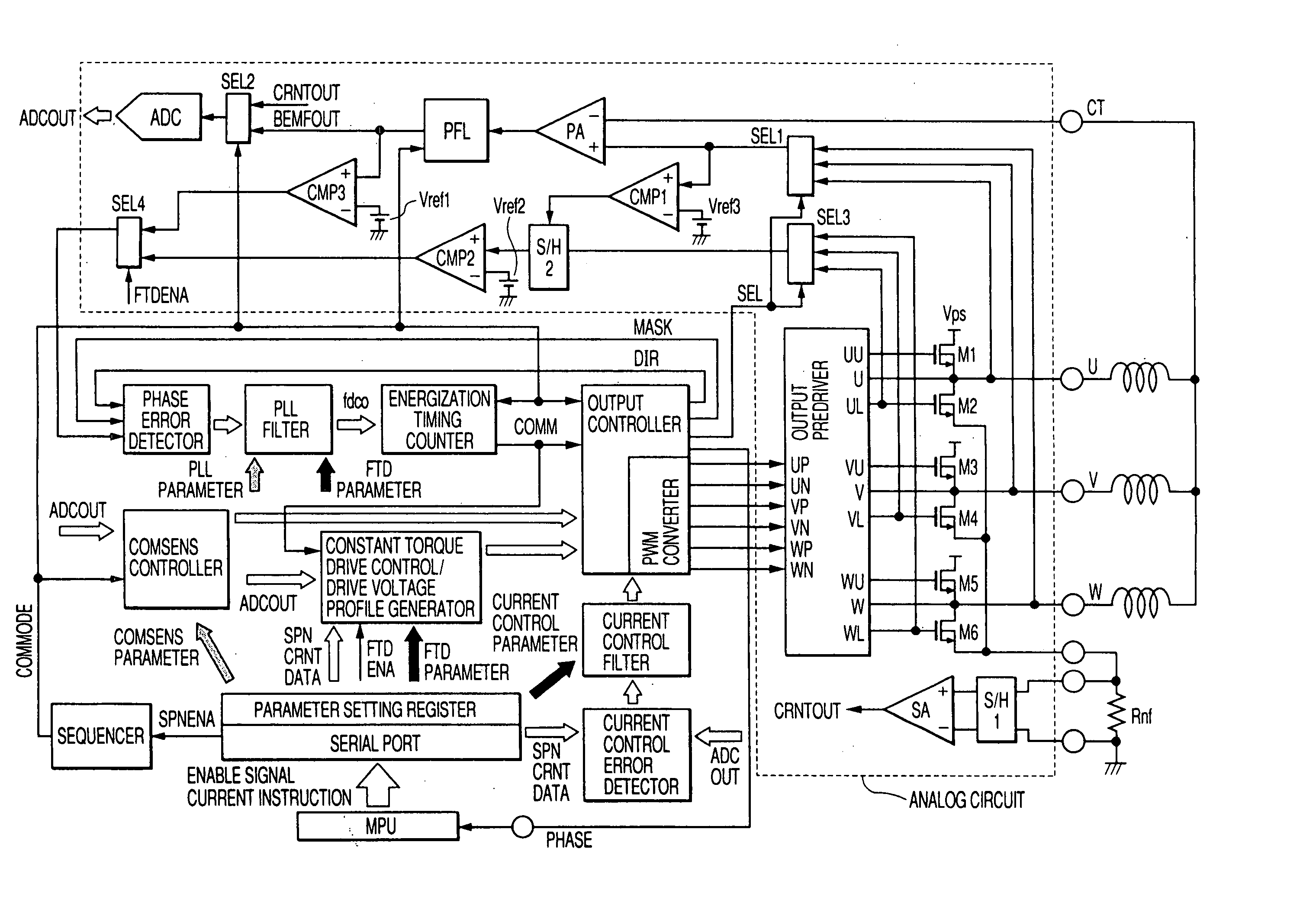
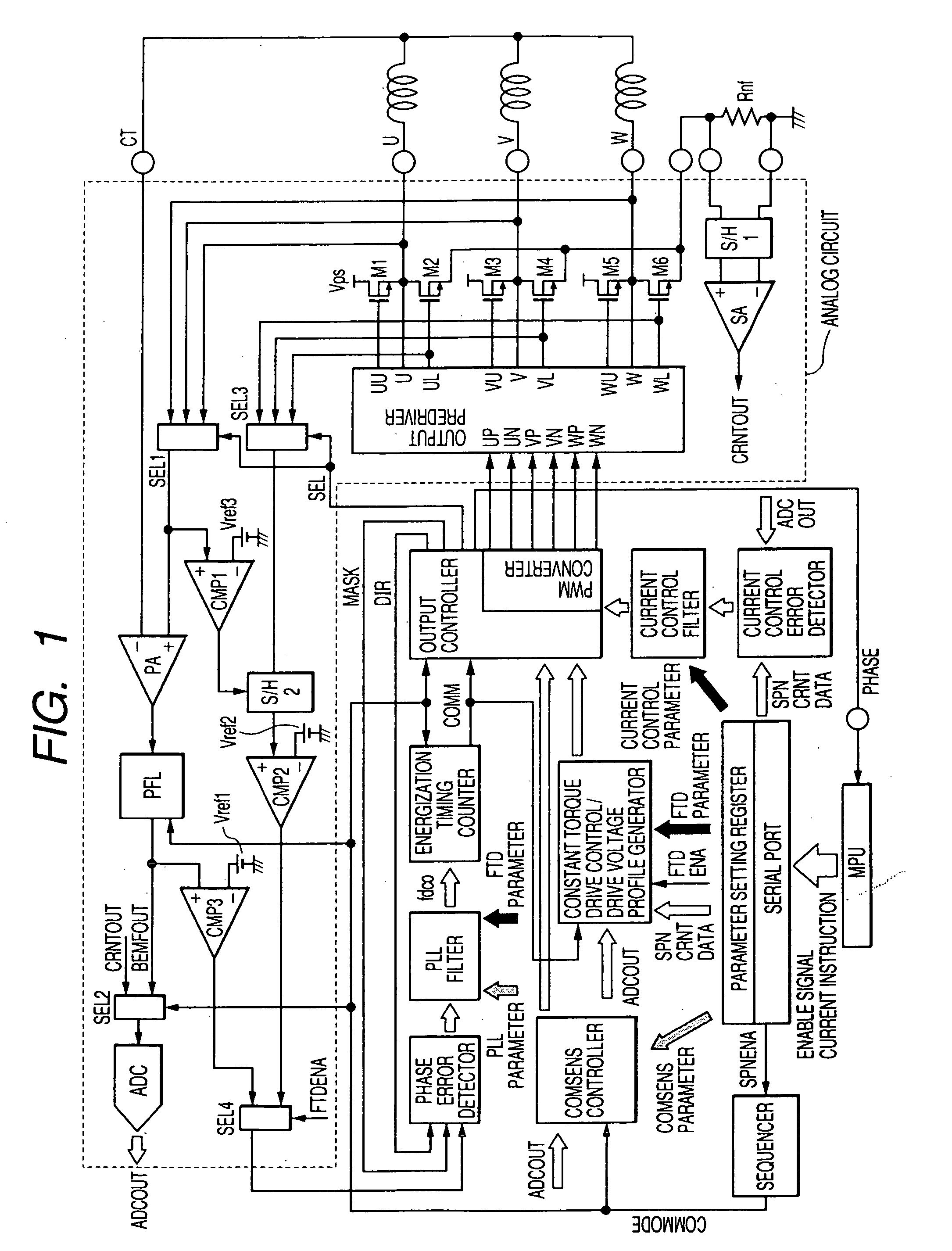
[0032] A block diagram showing one embodiment of a motor drive device according to the present invention is shown in FIG. 1. The present embodiment is intended for constant torque driving of a three-phase motor used as a multiphase motor based on 180-degree energization. Three-phase motor coils are driven based on pulse width modulation (PWM) signals by an output stage comprising power elements such as power MOSFETs M1 through M6, and an output predriver. The predriver is operated with, as inputs, signals UP, UN, VP, VN, WP and WN obtained by PWM-modulating sine wave-like drive voltages generated from a drive voltage profile generator by an output controller.

[0033] A selector SELL selects a BEMF (Back ElectroMotive Force) detected phase from spindle output voltages U, V and W, and a preamplifier PA generates a voltage corresponding to the differ...


PUM

PropertyMeasurementUnit
electrical angleaaaaaaaaaa
threshold voltageaaaaaaaaaa
electrical angleaaaaaaaaaa

Abstract

A three-phase DC motor output stage including a predriver that supplies drive voltages to power MOSFETs supplies output voltages to three-phase coils, monitors whether each of gate-to-source voltages of the power MOSFETs is greater than or equal to a predetermined voltage and thereby detects a current zero cross, and employs the output of such current zero cross detection in PLL control for controlling energization switching timing and thereby forms drive voltages of 180-degree energization. Lower hooks with a voltage minimum phase as GND and upper hooks with a voltage maximum phase as a source are set as patterns alternately repeated for every electrical angle of 60 degrees. The patterns are expressed in linear approximation to generate sine wave-like drive voltages, thereby causing sine wave-like currents to flow into the three-phase coils.

Description

CROSS-REFERENCE TO RELATED APPLICATION [0001] The present application claims priority from Japanese patent application No. 2003-335412 filed on Sep. 26, 2003, the content of which is hereby incorporated by reference into this application. BACKGROUND OF THE INVENTION [0002] The present invention relates to a motor drive device and an integrated circuit device for motor driving, and to a technique effective if applied to a rotation control technique for a three-phase spindle motor of HDD (Hard Disk Driver) or the like. [0003] As a system for driving a spindle motor of an HDD system, a soft switch system has been adopted which performs PWM corresponding to two phases upon energized-phase switching to thereby suppress a steep change in current. Although it is necessary to detect the position of a motor for the purpose of rotating the motor, it is known as a sensorless system that a de-energization period is provided after the energized-phase switching to detect a back electromotive forc...

Claims


Application Information

Patent Timeline
Patent Type & Authority Applications(United States)
IPC IPC(8): H02P7/06H02P6/06G11B19/28H02P6/08H02P6/10H02P6/16H02P6/17H02P6/28
CPCG11B19/28
Inventor KUROSAWA, MINORUKOKAMI, YASUHIKO
Owner RENESAS ELECTRONICS CORP
Why Eureka
Try Eureka