
Liquid crystal display

Active Publication Date: 2006-07-20
TIVO LLC
View PDF38 Cites 47 Cited by
  • Summary
  • Abstract
  • Description
  • Claims
  • Application Information

AI Technical Summary

Benefits of technology

[0020] An object of the present invention is to provide a liquid crystal display, which can prevent deterioration of display quality by suppressing variations in gamma characteristics, even when a mode for driving a liquid crystal display panel is switched between an impulse drive mode and a hold drive mode.
[0026] In the liquid crystal display of the present invention, in accordance with a selected drive mode (impulse drive mode or hold drive mode), a gradation voltage to be applied to the liquid crystal display panel varies corresponding to input image data. Therefore, it is possible to prevent variations in gamma characteristics, which is caused by differences in response speed of the liquid crystal between display gradations, when certain monochrome display is carried out. Thus, it is possible to prevent deterioration of display quality, which occurs when the impulse display mode and the hold display mode are switched.
[0027] According to a mode for driving the liquid crystal display panel, the driving means varies a reference gradation voltage itself for driving the liquid crystal display panel. Thus, display capability of the liquid crystal display panel can be maintained and high-quality display can be realized. Further, gamma characteristics due to the temperature dependency of the liquid crystal can be also suppressed, so that high-quality display can be always achieved.

Problems solved by technology

The cause of this problem is a slow response of liquid crystal material.
Not only the delay of the optical response time, but also an LCD display system itself are pointed out as causes of motion blur in movie display.
Thus, the motion blur occurs.
Thus, display quality significantly deteriorates.
That is, gamma characteristics change depending on temperatures of the liquid crystal display panel, so that display quality varies (deteriorates).

Method used


Image

  • Liquid crystal display
  • Liquid crystal display
  • Liquid crystal display

Examples


Embodiment Construction

[0051] The following more specifically describes the present invention through examples and comparative examples. However, the present invention is not limited by the examples and comparative examples.

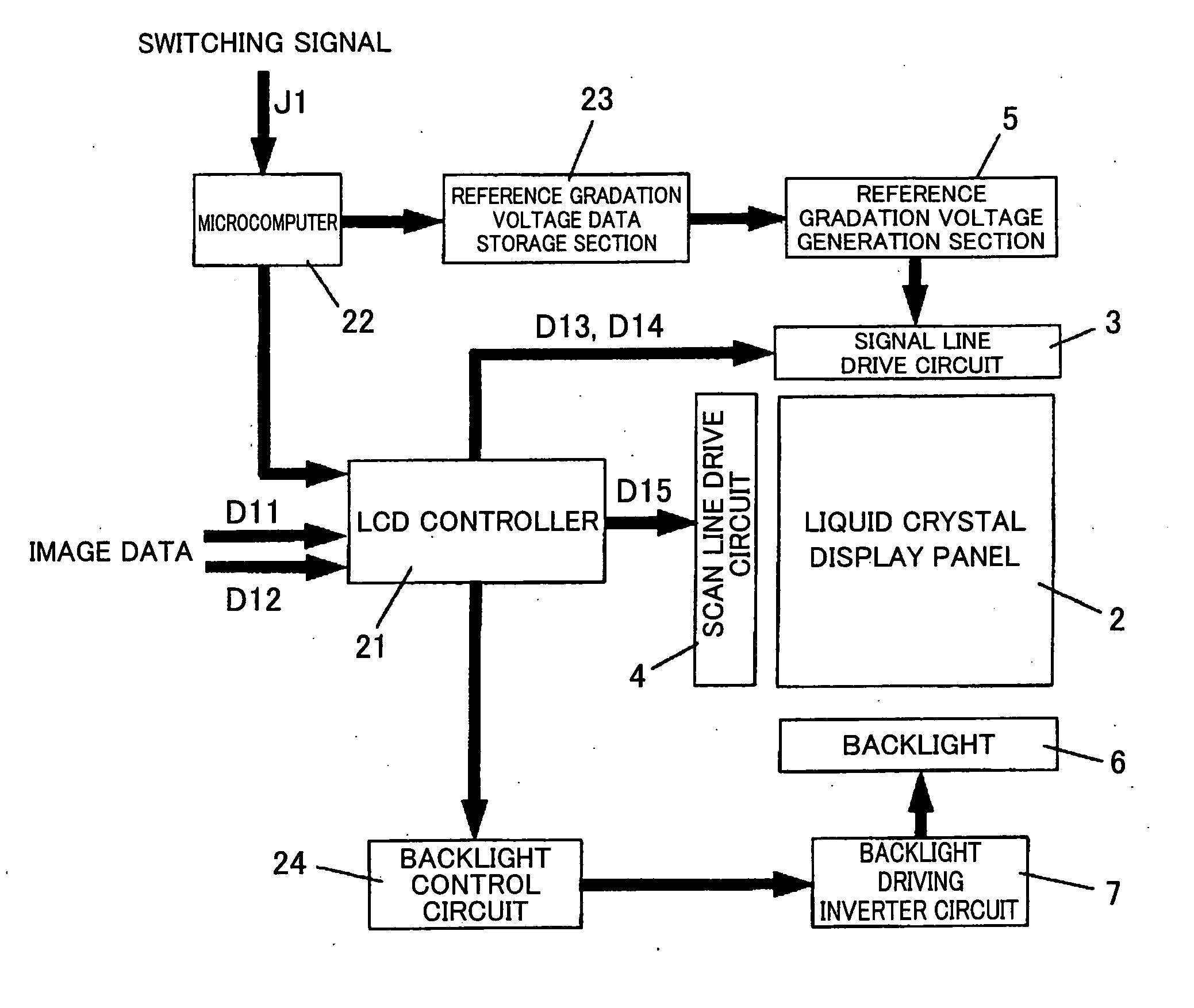
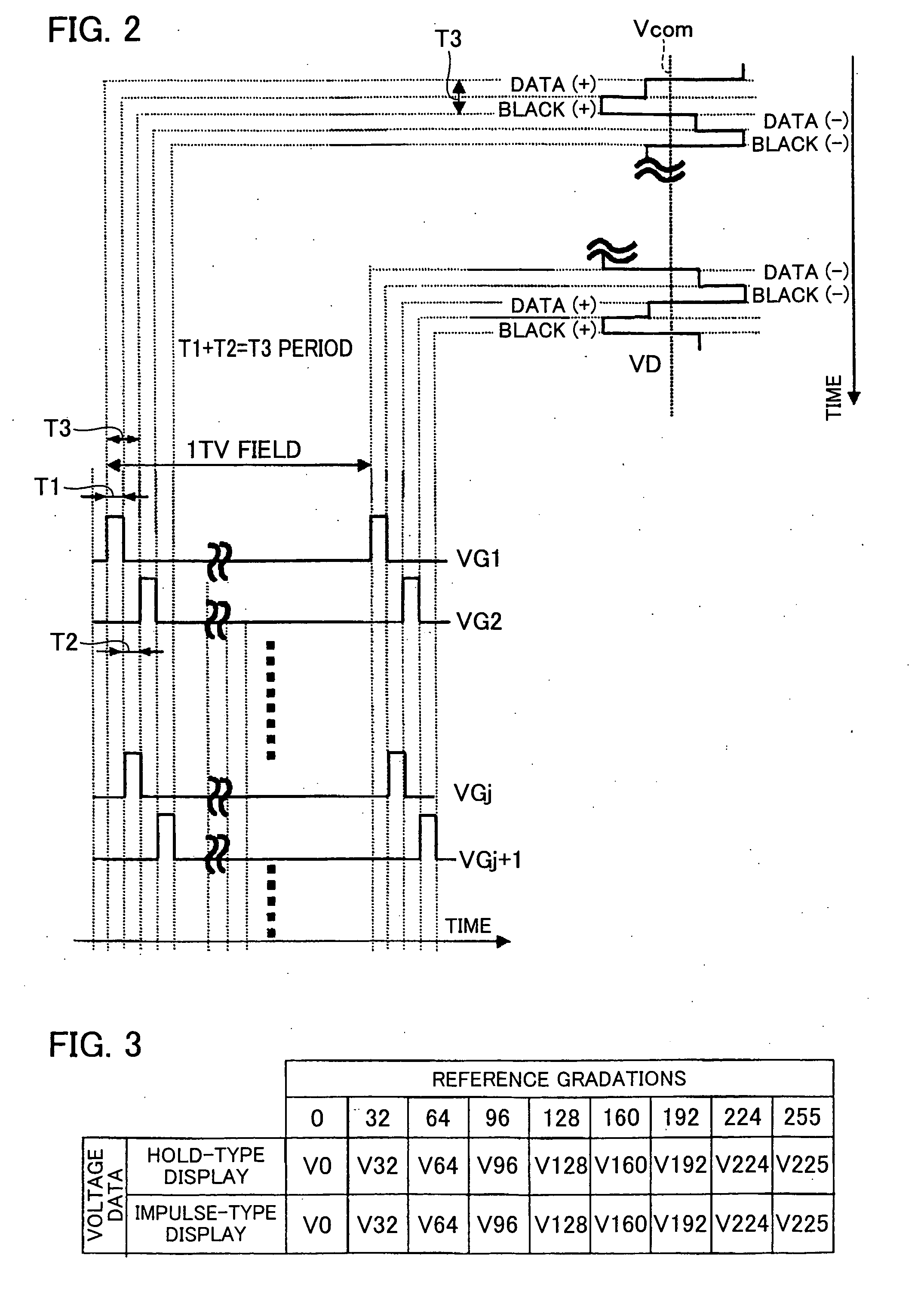
[0052] With reference to FIGS. 1 through 7, a first embodiment of the present invention is described below. The same numbers are used for the same parts with the conventional examples, and their explanations are omitted. FIG. 1 is a block diagram illustrating a schematic structure of the liquid crystal display of the present embodiment. FIG. 2 is an explanatory diagram illustrating one example of drive signal waveforms in the impulse-type display in the liquid crystal display of the present embodiment. FIG. 3 is a schematic explanatory view showing specific examples of the reference gradation voltage data storage section in the liquid crystal display of the present embodiment.

[0053]FIG. 4 is a schematic explanatory view expressing response characteristics of the liquid crystal in the...


PUM


Abstract

A liquid crystal display has an LCD controller, a microcomputer, and a storage section. The LCD controller is capable of setting up an image display period for performing display based on input image data and a black display period for performing display based on black display data, within one field period. The microcomputer switches the mode of the LCD controller between an impulse-drive mode having the image display period and the black display period within the one field period, and a hold drive mode having only the image display period. The storage section stores sets of reference gradation voltage data that are previously specified. A reference gradation voltage, which is generated at a reference gradation voltage generation section and used for driving the liquid crystal display panel, is variable according to the mode. Thus, it is possible to realize the liquid crystal display that can suppress changes in gamma characteristics so as to prevent deterioration of display quality even when the mode is switched.

Description

TECHNICAL FIELD [0001] The present invention relates to a liquid crystal display which displays images by using a liquid crystal display panel. More particularly, the present invention relates to a liquid crystal display capable of improving deterioration of display quality of moving images, which is caused by response characteristics of the liquid crystal display panel. BACKGROUND ART [0002] In these years, there have been needs for reductions in weight and thickness of personal computers and TV sets. According to such needs, flat-panel displays such as liquid crystal displays (LCD) have been developed, as substitutes for cathode-ray tubes (CRT). [0003] An LCD is a display that applies an electric field to a liquid crystal layer having anisotropic permittivity (anisotropic dielectric constant), the liquid crystal layer being interposed between two substrates. By adjusting the electric field, the LCD controls a volume of light passing through the substrates so as to obtain desired i...

Claims


Application Information

Patent Timeline
IPC IPC(8): G09G3/36G09G3/20G09G3/34
CPCG09G3/2014G09G3/3611G09G2310/061G09G2320/0673G09G2320/0252G09G2320/0261G09G2320/0613G09G2320/0247G02F1/133G09G3/20G09G3/36
Inventor FUJINE, TOSHIYUKI
Owner TIVO LLC
Learn More