Printable electronic features on non-uniform substrate and processes for making same

a technology of electronic features and substrates, applied in the field of direct printing, can solve the problems of high cost of machinery, high cost of set-up and maintenance, and labor of skilled laborers

Inactive Publication Date: 2006-07-20
CABOT CORP
View PDF100 Cites 46 Cited by
  • Summary
  • Abstract
  • Description
  • Claims
  • Application Information

AI Technical Summary

Benefits of technology

[0029] It is therefore a general object of the invention to provide a non-contact direct printing sys

Problems solved by technology

As one of ordinary skill in the art can appreciate, the lithographic or offset printing process described above in reference to FIGS. 1 and 2 is complicated, involves skilled laborers, and requires very costly machinery, which requires expensive set-up and maintenance.
In addition to these significant drawbacks, the lithographic or offset printing system does not print well on non-uniform substrates, whether they are paper or other materials.
In some circumstances, use of the lithographic or offset printing system could be detrimental to the actual substrate material itself.
Thus, there are significant problems with use of the lithographic or offset printing process on many types of substrate materials.
For example, for even applying simple images to a wafer substrate, as might be done on silicon solar cells, there are numerous steps that involve very expensive machines and very well trained personnel to run the expensive machines.
As one of ordinary skill in the art can appreciate from the discussion above, there are significant drawbacks for use of photolithography when printing images on semiconductor wafers 30.
Printing on the transistors can only be accomplished by vacuum deposition.
In addition to the expensive photolithographic tools already discussed, vacuum deposition requires additional and expensive machinery, and a significant amount of steps to accomplish the process.
Further, skilled workers, which are needed to run the expensive machinery, add to the overall production costs.
Screen printing is a very old, but commonly used technology that involves relatively inexpensive equipment, but still presents difficulties in practical usage in some applications.
There are, however, many difficulties that can be encountered when using the screen mesh printing process with non-uniform and other substrate materials.
For example, printing high-resolution patterns into rece

Method used


Image

  • Printable electronic features on non-uniform substrate and processes for making same
  • Printable electronic features on non-uniform substrate and processes for making same
  • Printable electronic features on non-uniform substrate and processes for making same

Examples


Embodiment Construction

[0110] The various features of the preferred embodiment(s) will now be described with reference to the drawing figures, in which like parts are identified with the same reference characters. The following description of the presently contemplated best mode of practicing the invention is not to be taken in a limiting sense, but is provided merely for the purpose of describing the general principles of the invention.

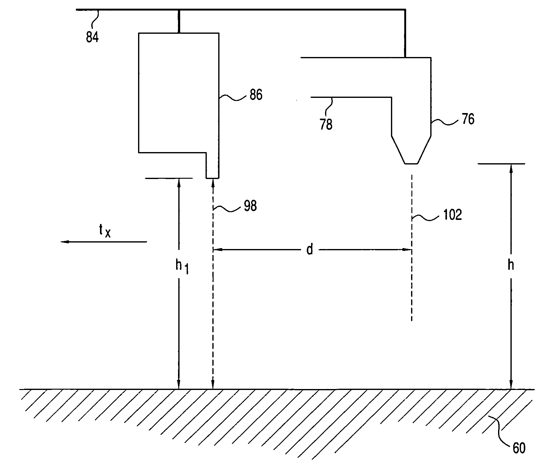
[0111]FIG. 13 illustrates a partial side view of a direct printing system 100 expelling a drop of ink (ink drop) 74 according to an embodiment of the present invention. In the direct print system 100 shown in FIG. 13, a nozzle 76 is expelling an ink drop 74 at a height h above a substrate 60. The direct printing system 100 can determine the velocity of each ink drop 74 as it is expelled from the nozzle 76. The velocity of the drop of expelled ink 74 is denoted as VD. In addition, as is well known to those of ordinary skill in the art, the nozzle 76 moves with the print he...


PUM


Abstract

A system and process for compensating for non-uniform surfaces of a substrate when direct printing traces is provided. The system and process provided herein measures the surface of a substrate and can determine whether the surface is substantially flat, rises or falls, or whether a mesa or valley is encountered. Depending on the surface feature (i.e., mesa, valley, falling or rising surface), the direct printing system can change the frequency of the printing timing signal, advance or retard the print timing signal, advance or retard the print data, or make repeated passes over certain areas. In addition, the process disclosed herein can determine whether two, three or all of the aforementioned steps for compensating for non-uniform substrates should be combined to most effectively and efficiently print on the non-uniform surface of the substrate as intended.

Description

CROSS REFERENCE TO RELATED APPLICATIONS [0001] This application claims priority to U.S. Provisional Patent Applications Ser. No. 60 / 695,404 filed Jul. 1, 2005, 60 / 643,577, 60 / 643,629, and 60 / 643,378, all filed on Jan. 14, 2005, the entireties of which are incorporated herein by reference.BACKGROUND OF THE INVENTION [0002] 1. Field of the Invention [0003] The invention relates to direct printing. More particularly, the invention relates to a system and method for non-contact direct printing using conductive particles in an ink solution for dispersion on non-uniform substrates. [0004] 2. Background Art [0005] Traditional deposition technologies, such as photolithography and screen-printing, both of which are discussed below, are restricted to planar substrates. FIG. 1 illustrates an emulsion exposure process step for lithography printing according to the prior art, and FIG. 2 illustrates a simplified side view of a lithographic printing system according to the prior art. [0006] The li...

Claims


Application Information

Patent Timeline
IPC IPC(8): B41J25/308
CPCB41J3/4073B41J25/308H05K1/0284H05K3/125H05K2203/013H05K2203/163
Inventor VANHEUSDEN, KARELEDWARDS, CHUCK
Owner CABOT CORP
Why Eureka
Try Eureka