
Liquid crystal display apparatus and electronic apparatus

Active Publication Date: 2006-07-20
BOE TECH GRP CO LTD
View PDF2 Cites 16 Cited by
  • Summary
  • Abstract
  • Description
  • Claims
  • Application Information

AI Technical Summary

Benefits of technology

[0007] An advantage of the invention is that it provides a liquid crystal display apparatus including a viewing angle controlling member capable of ensuring a wide viewing angle controlling range or changing states in comparison to a conventional technique.
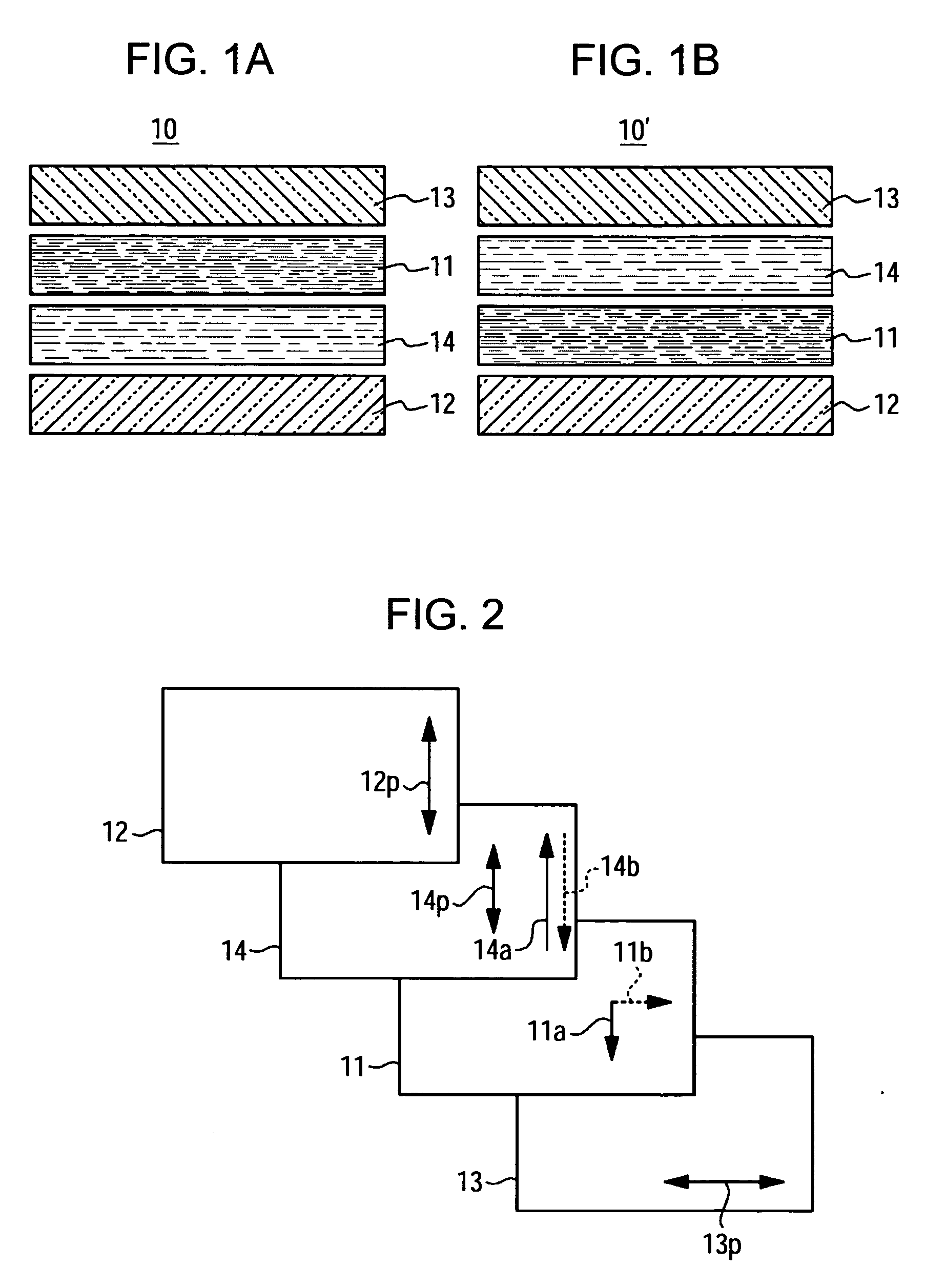
[0008] According to an aspect of the present invention, there is provided a liquid crystal display apparatus having a displaying liquid crystal layer, a displaying electric field applying structure for applying a displaying electric field to the displaying liquid crystal layer, and a pair of polarizing layers sandwiching the displaying liquid crystal layer therebetween, the liquid crystal display apparatus comprising: a viewing-angle controlling liquid crystal layer disposed between one of the polarizing layers and the displaying liquid crystal layer; and a viewing-angle controlling electric field applying structure for applying a viewing-angle controlling electric field to the viewing-angle controlling liquid crystal layer, wherein the viewing-angle controlling liquid crystal layer is constructed to change between horizontal and vertical alignment states, and wherein a slow axis in the horizontal alignment state of the viewing-angle controlling liquid crystal layer is disposed in parallel to a polarized-light transmitting or absorbing axis of the polarizing layer disposed opposite to the displaying liquid crystal layer with respect to the viewing-angle controlling liquid crystal layer.
[0009] According to the present invention, since the viewing-angle controlling liquid crystal layer is constructed to change between substantially uniform horizontal and vertical alignment states, and since the slow axis in the horizontal alignment state is disposed to substantially parallel to the polarized-light transmitting or absorbing axis of a polarizing layer (an adjacent polarizing layer) disposed at the opposite to the display liquid crystal layer, an influence of the viewing-angle controlling liquid crystal layer in the horizontal alignment state on the distribution of the polar angle of transmittance can be semantically removed, so that the viewing angle cannot be limited by maintaining the viewing-angle controlling liquid crystal layer in the horizontal alignment state. On the other hand, since the polarization state of the light incident in a slanted direction changes in the vertical alignment state, a use efficiency of light decreases or light leakage increase in a portion where the polar angle is high, so that the contrast ratio can be greatly reduced in comparison to the conventional technique. As a result, the viewing angle limitation effect can be improved.
[0010] In the aforementioned aspect of the present invention, the viewing-angle controlling liquid crystal layer may in a horizontal alignment state when no electric field is applied by the viewing-angle controlling electric field applying structure, and the viewing-angle controlling liquid crystal layer may be in a vertical alignment state when an electric field is applied. In this case, since the horizontal alignment state is initially aligned, the slow axis in the horizontal alignment state can be easily defined to be the polarized-light transmitting or absorbing axis of the polarizing layer, and the directions of the axes can be easily and accurately defined.
[0011] In addition, the viewing-angle controlling liquid crystal layer may be in a vertical alignment state when no electric field is applied by the viewing-angle controlling electric field applying structure, and the viewing-angle controlling liquid crystal layer may be in a horizontal alignment state when an electric field is applied. By doing so, since the vertical alignment state of the viewing-angle controlling liquid crystal layer can be easily defined, an optical state in case of limiting the viewing angle can be easily and accurately defined.
[0012] In addition, an alignment azimuth angle in the horizontal alignment state of the viewing-angle controlling liquid crystal layer may be defined as four directions which are substantially parallel to the polarized-light transmitting and absorbing axes. By doing so, since the slow axis of the viewing-angle controlling liquid crystal layer in the horizontal alignment state is defined to be four directions parallel to any one of the polarized-light transmitting and absorbing axes, the aforementioned basic conditions of the present invention are satisfied, and the liquid crystal molecules are directed at a plurality of the alignment azimuth angles, so that azimuth angel dependency of optical characteristics can be surely reduced when the viewing-angle controlling liquid crystal layer is in the horizontal alignment state. In this case, the four directions of the viewing-angle controlling liquid crystal layer in the horizontal alignment state can be defined by using alignment limiting members such as protrusions, slits (electrode openings), and ribs for limiting an inverse alignment directions of the liquid crystal molecules.

Problems solved by technology

However, in a case where many persons intend to be allowed to see the display screen, since the viewing angel cannot be widened, the conventional methods are inconvenient.
However, in the liquid crystal display apparatus using the aforementioned phase difference controlling liquid crystal device, although a range where a contrast ratio becomes 10:1 is slightly narrow due to the switching of the phase difference controlling liquid crystal device, there are problems in that a boundary value of a polar angle in the associated range is about 50% to 70% of the before-switching one, a whole change in the contrast is small, and it is difficult to sufficiently control viewing angle.
In particular, since sufficient viewing can be generally obtained with a contrast ratio of about 2:1, the aforementioned technique is not a practical display technique for preventing persons existing at left and right side from viewing the display screen by limiting the viewing angle.

Method used


Image

  • Liquid crystal display apparatus and electronic apparatus
  • Liquid crystal display apparatus and electronic apparatus
  • Liquid crystal display apparatus and electronic apparatus

Examples


first embodiment

[0035] Now, a first embodiment of the present invention will be described in detail with reference to the accompanying drawings. FIG. 1 is a schematic constructional view showing a basic construction of a liquid crystal display apparatus according to the embodiment. In the basic construction 10 shown in FIG. 1A, a pair of polarizing layer 12 an 13 sandwich a displaying liquid crystal layer 11 therebetween, and a viewing-angle controlling liquid crystal layer 14 is disposed between the polarizing layer 12 of an incident light side (that is, a lower one shown in the figure) and the displaying liquid crystal layer 11. In the construction 10, a light incident from a light source such as a backlight becomes a linearly polarized light having a vibrating plane parallel to the polarized-light transmitting axis of the polarizing layer 12, and after that, optically modulated by the viewing-angle controlling liquid crystal layer 14. Subsequently, the light is subject to optical modulation for ...

second embodiment

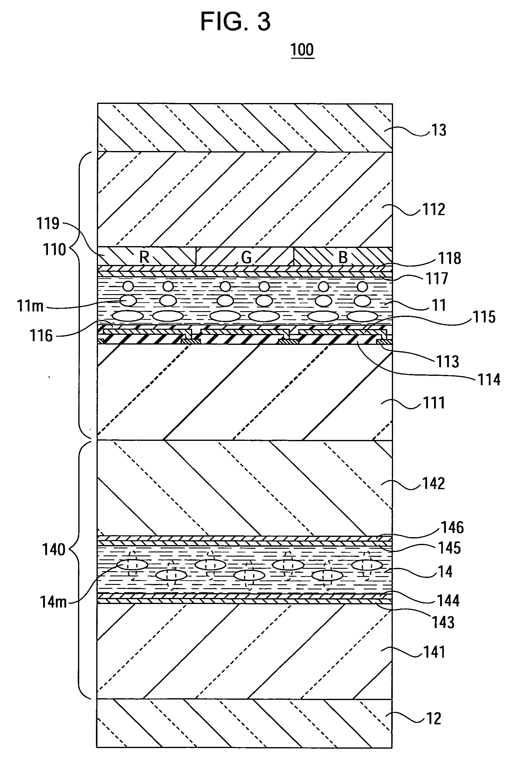
[0056] Now, a liquid crystal display apparatus 200 according to a second embodiment of the present invention will be described with reference to FIG. 8. The embodiment is different from the first embodiment in that the displaying liquid crystal cell 210 is in a vertical aligned mode, an initial alignment state of a viewing-angle controlling liquid crystal cell 240 is a vertical alignment state, the alignment state thereof becomes a horizontal alignment state when an electric field is applied thereto, and phase difference layers 21A and 21B are disposed at both sides of the displaying liquid crystal cell 210. However, the viewing-angle controlling liquid crystal cell 240 may has the same structure as the viewing-angle controlling liquid crystal cell 140 of the first embodiment.

[0057] In the displaying liquid crystal cell 210 of the embodiment, retardation Δn·d of a displaying liquid crystal layer 21 is defined to be 0.42 μm by using a liquid crystal (a nematic liquid crystal) having...

third embodiment

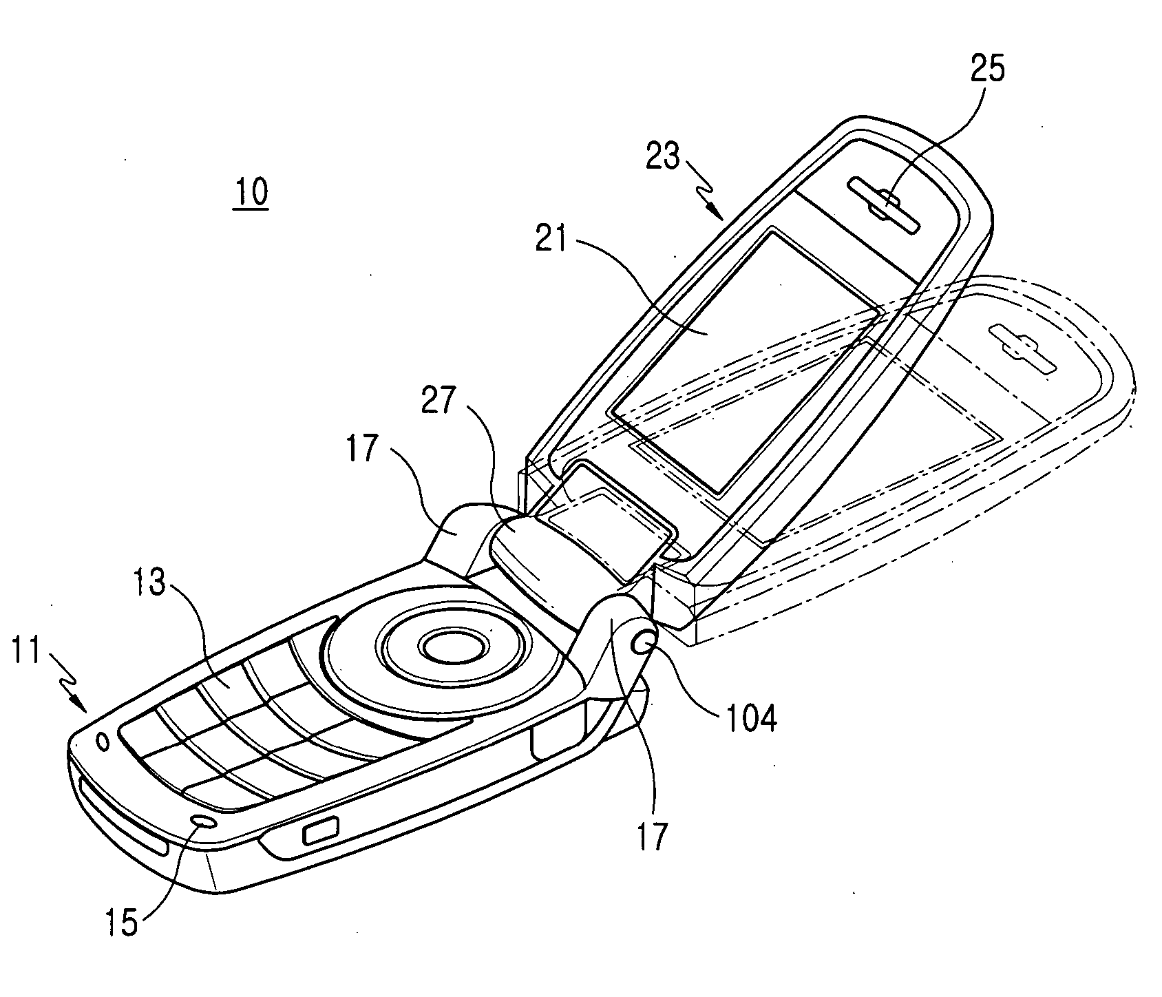
[0070] Finally, an electronic apparatus which the aforementioned liquid crystal display apparatus is built in will be described. FIG. 18A shows an outer appearance of a mobile phone as an example of an electronic apparatus 1000 (a portable electronic apparatus) according to the present invention, and FIG. 8B shows a display screen 100DP of the associated electronic apparatus 1000. As shown in FIG. 18A, an operation portion 1001 and a display portion 1002 are provided to the electronic apparatus 1000, and the operation portion 1001 and the display portion 1002 are allowed to be folded. A circuit board 1003 is received in the display portion 1002, the liquid crystal display apparatus 100 is mounted on the display portion 1002, and the display screen 100DP is exposed to a surface of the display portion 1002.

[0071] As shown in FIG. 18B, in the display screen 100DP of the liquid crystal display apparatus 100, the polarized-light transmitting axis 14p of the polarizing layer 12 adjacent ...


PUM


Abstract

A liquid crystal display apparatus includes a viewing-angle controlling liquid crystal layer that, when in a horizontal alignment state, exhibits a slow axis that is parallel to a polarized-light transmitting or absorbing axis of a polarizing layer that is disposed opposite to the displaying liquid crystal layer from the viewing-angle controlling liquid crystal layer.

Description

BACKGROUND [0001] 1. Technical Field [0002] The present invention relates a liquid crystal display apparatus and an electronic apparatus, and more particularly, to a construction of a liquid crystal display apparatus suitable for a display apparatus capable of limiting a viewing angle range of a display screen. [0003] 2. Related Art [0004] In general, there is a case where an owner of a mobile phone or other portable information terminals with a liquid crystal display apparatus built in intends to see a display screen of the liquid crystal display apparatus while preventing other persons from seeing the display screen. In this case, conventionally, a narrow viewing angle display device has been used, or an optical film for limiting the viewing angle has been attached on the display screen. However, in a case where many persons intend to be allowed to see the display screen, since the viewing angel cannot be widened, the conventional methods are inconvenient. [0005] Therefore, an app...

Claims


Application Information

Patent Timeline
IPC IPC(8): G02F1/1335
CPCG02F1/1323G02F1/13363G02F1/13471A47J19/06A47J19/02A47J43/07
Inventor MATSUSHIMA, TOSHIHARU
Owner BOE TECH GRP CO LTD
Learn More