Magnetic microspheres for use in fluorescence-based applications

Active Publication Date: 2006-07-20
LUMINEX
View PDF20 Cites 124 Cited by
  • Summary
  • Abstract
  • Description
  • Claims
  • Application Information

AI Technical Summary

Benefits of technology

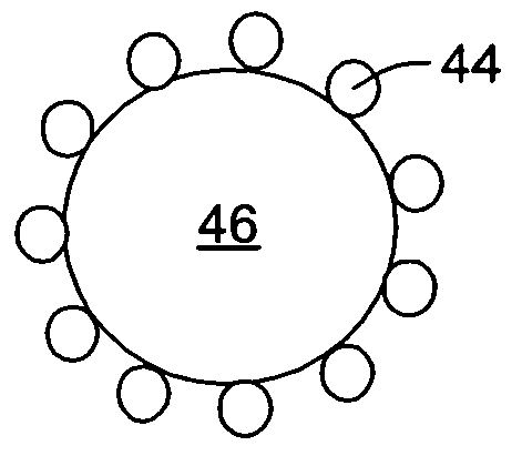
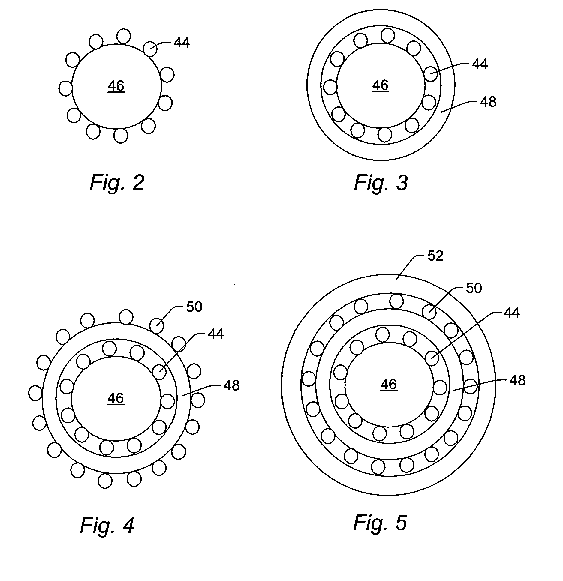
[0025] The microsphere embodiments described above provide several advantages over currently used microspheres having magnetic and fluorescent properties. For example, the microsphere described above can include greater than about 2% by weight of the magnetic material without significantly hindering light transmission into and out of the microsphere. In particular, it has been determined that when more than about 50% of the surface of the core microsphere is obscured by the magnetic material, the fluorescent emission of the microsphere b

Problems solved by technology

This retention of domain alignment may lead to microsphere aggregation in the absence of an external magnetic field, which is often undesirable.
These methods are relatively simple approaches to the synthesis of fluorescent magnetic microspheres, but are not suitable for creating the large numbers of precisely dyed microspheres used in relatively large multiplex assays such as those as described in U.S. Pat. No. 5,981,180 to Chandler et al.
This limitation of the methods of Wang et al. is due to the fact that most fluorescent dye molecules are extremely sensitive to attack by radical species generated during radical initiation polymerizations.
If these radicals inactivate even a relatively small number of dye molecules, precise quantities of dye in the microspheres cannot be achieved.
This method produces microspheres with desirable characteristics, but the nanosphere-microsphere bond may be susceptible to cleavage under severe reaction conditions.
A coating surrounding the microsphere and nanospheres bound thereto may be used to improve this association but, again, the use of radical initiators to form this coating can compromis

Method used


Image

  • Magnetic microspheres for use in fluorescence-based applications
  • Magnetic microspheres for use in fluorescence-based applications
  • Magnetic microspheres for use in fluorescence-based applications

Examples


example 1

Preparation of Magnetite

[0088] 0.2 moles of Iron (III) chloride hexahydrate and 0.1 mole of iron (II) chloride tetrahydrate were dissolved in 400 ml of deionized water in a three-neck round bottom flask with overhead stirring. This mixture was heated to 90° C. with continued stirring. 520 ml of 6N NaOH was added dropwise over 1 hour. The reaction was allowed to continue for 24 hours.

example 2

Magnetite and Polymer Coating

[0089] 10.2 g of commercially available polystyrene core microspheres with a functionalized carboxylated surface modification were suspended in a total volume of 100 ml methanol. 12.4 ml of the prepared magnetite solution was washed with deionized water, followed by two washes in 1M HCL, and finally two washes with methanol. Each wash step was followed by centrifugation at approximately 4000×g to separate the larger magnetite particles from the smaller magnetic particles. The magnetite was resuspended in a total volume of 100 ml of methanol. The magnetite and the core microspheres were combined and allowed to mix for 3 hours. This mixture was then washed four times with deionized water, and then resuspended in a total volume of 375 ml of water and charged to a 500 ml three-neck round bottom flask.

[0090] A mixture of 12.6 g distilled styrene, 0.768 g distilled divinylbenzene, 0.173 g benzoyl peroxide, and 1.47 g acrylic acid was prepared and charged to ...


PUM

PropertyMeasurementUnit
Fractionaaaaaaaaaa
Sizeaaaaaaaaaa
Sizeaaaaaaaaaa

Abstract

Microspheres, populations of microspheres, and methods for forming microspheres are provided. One microsphere configured to exhibit fluorescent and magnetic properties includes a core microsphere and a magnetic material coupled to a surface of the core microsphere. About 50% or less of the surface of the core microsphere is covered by the magnetic material. The microsphere also includes a polymer layer surrounding the magnetic material and the core microsphere. One population of microspheres configured to exhibit fluorescent and magnetic properties includes two or more subsets of microspheres. The two or more subsets of microspheres are configured to exhibit different fluorescent and/or magnetic properties. Individual microspheres in the two or more subsets are configured as described above.

Description

PRIORITY APPLICATION [0001] This application claims priority to U.S. Ser. No. 60 / 645,549 entitled “Magnetic Microspheres for use in Fluorescence-Based Application” filed Jan. 20, 2006.BACKGROUND OF THE INVENTION [0002] 1. Field of the Invention [0003] The present invention generally relates to magnetic microspheres for use in fluorescence-based applications. Certain embodiments relate to a microsphere that includes a magnetic material coupled to a surface of a core microsphere and a polymer layer surrounding the magnetic material and the core microsphere. [0004] 2. Description of the Related Art [0005] The following description and examples are not admitted to be prior art by virtue of their inclusion in this section. [0006] Magnetic microspheres are currently used in a wide variety of applications, including: hyperthermic treatment of tumors; directed delivery of therapeutic substances to target locations in living systems; cell, polynucleotide, and protein isolation; and clinical ...

Claims


Application Information

Patent Timeline
IPC IPC(8): B32B15/00H01F1/00C09K11/06
CPCB82Y25/00H01F1/0018H01F1/0036H01F1/063H01F1/111H01F1/36Y10T428/2993G01N21/6486Y10T428/2995Y10T428/2998Y10T428/32Y10T428/2996Y10T428/2991G01N21/64C09K11/025C09K11/06G01N33/543G01N33/58H01F1/06G01N21/6428G01N33/54326H01F1/0315
Inventor CHANDLER, DON J.BEDRE, JASON
Owner LUMINEX
Why Eureka
Try Eureka