
Rapid prototyping and manufacturing of photocured objects using LCD panel as programmably variable photomask

a technology of photocurable polymer and lcd panel, which is applied in the direction of program control, process and machine control, instruments, etc., can solve the problems of high resolution of lithography, slow system, high cost and slowness of quality objects, etc., and achieve the effect of rapid prototyping and manufacturing

Inactive Publication Date: 2006-07-20
SIMONIS STEVEN F
View PDF2 Cites 38 Cited by
  • Summary
  • Abstract
  • Description
  • Claims
  • Application Information

AI Technical Summary

Benefits of technology

[0011] The invention is an improved rapid prototyping and manufacturing system having a radiant energy source mounted for directing radiant energy toward an elevator platform descendible in a vat of photopolymer liquid under computer control for curing a layer of the photopolymer upon which the radiant energy is incident. The improvement is at least

Problems solved by technology

Although stereo lithography produces high resolution, quality objects, it is both expensive and slow.
The system is slow because the laser beam is directed to only one small spot at any instant of time and yet must spend sufficient time to fully cure the photocurable polymer at each spot in a two-dimensional grid array of contiguous spots in order to fully cure the entire cross-sectional layer.
While an object having an identical cross-sectional size and shape for all layers requires only a single photomask, most objects have a more complicated morphology and therefore require numerous photomasks.
Consequently, this system requires an extensive set up time for the preparation of the required photomasks.
Therefore, except for the most simple objects, solid ground curing requires considerable setup time for preparing the series of physical photomasks and requires operating time for exchanging or indexing the physical photomasks during processing.
The equipment is also expensive, though not as expensive as stereo lithography equipment, but it also requires the cost of the physical photomask material.

Method used


Image

  • Rapid prototyping and manufacturing of photocured objects using LCD panel as programmably variable photomask
  • Rapid prototyping and manufacturing of photocured objects using LCD panel as programmably variable photomask
  • Rapid prototyping and manufacturing of photocured objects using LCD panel as programmably variable photomask

Examples


Embodiment Construction

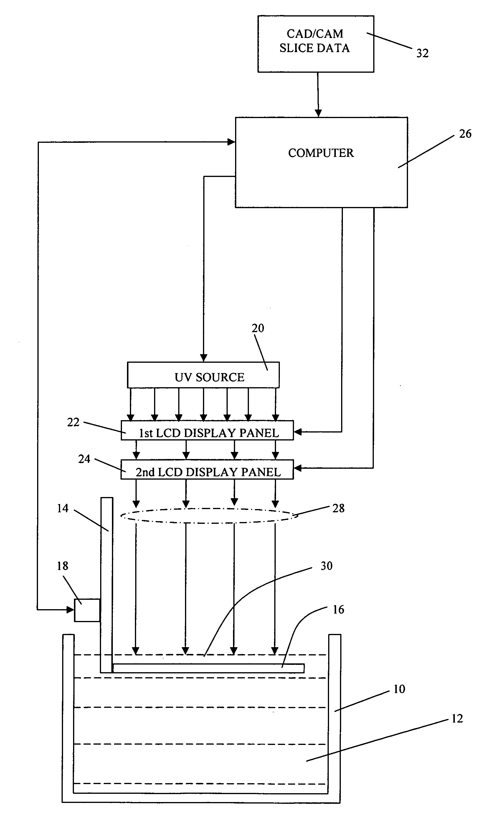
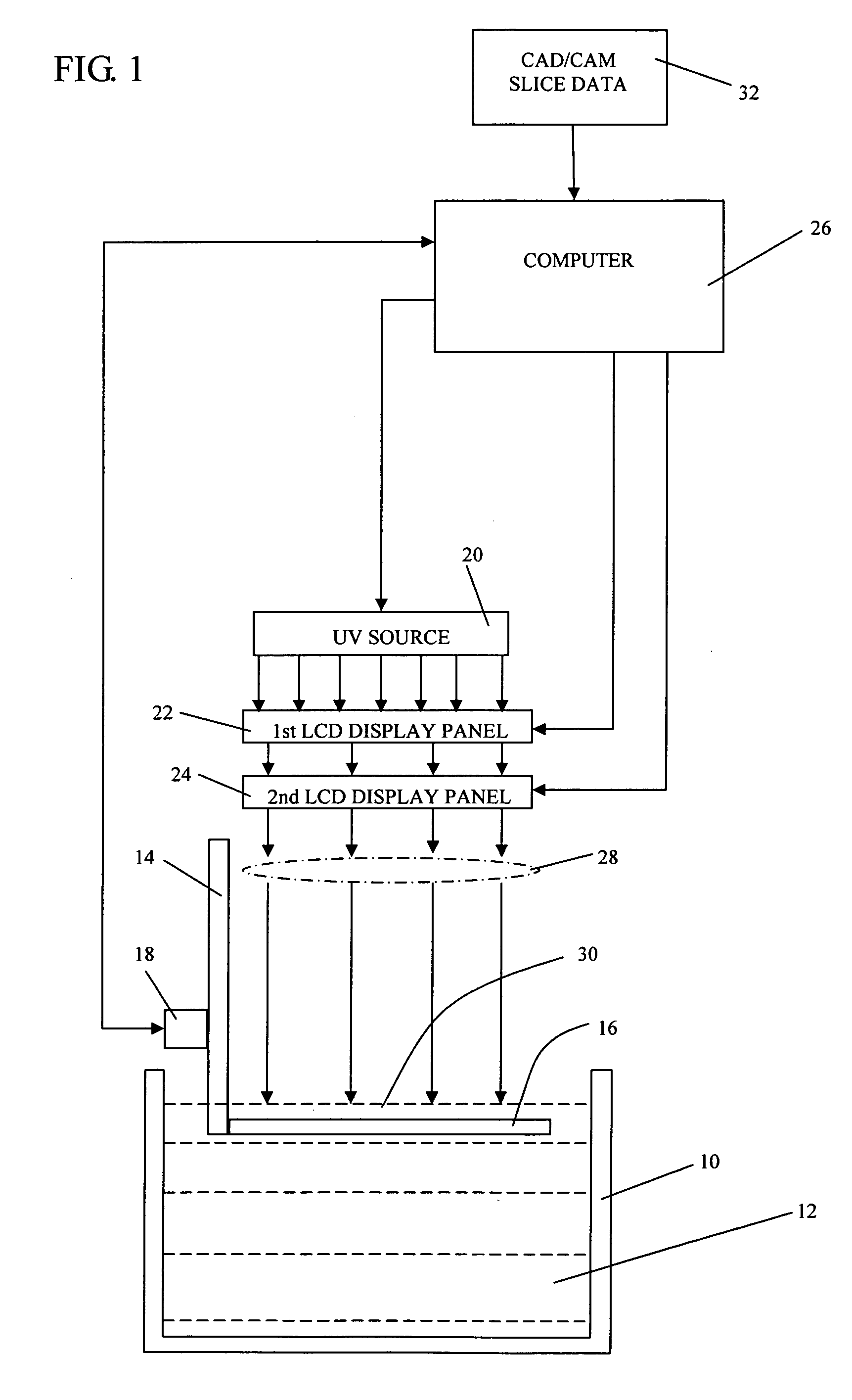
[0016]FIG. 1 illustrates the preferred embodiment of the invention. A vat 10 contains a liquid photopolymer 12. An elevator 14 mounted as a slidable carriage has a descendible platform 16 which is raised and lowered by a prime mover 18. The prime mover 18 may, for example, be a stepper motor driving the elevator through a worm gear and screw transmission. The above described components, as used in embodiments of the invention, are common to several rapid prototyping and manufacturing systems known in the prior art and therefore are not described in more detail.

[0017] Mounted above the platform 16 and arranged in generally vertical alignment are a UV light source 20 below which is mounted a primary liquid crystal display (LCD) panel 22 and a secondary LCD panel 24. An LCD panel is a two-dimensional grid array of contiguous liquid crystal pixels that is controlled by an electronic, digital data processing device and in the preferred embodiment of the invention by a computer 26. Ordin...


PUM

PropertyMeasurementUnit
Timeaaaaaaaaaa
Energyaaaaaaaaaa
Velocityaaaaaaaaaa

Abstract

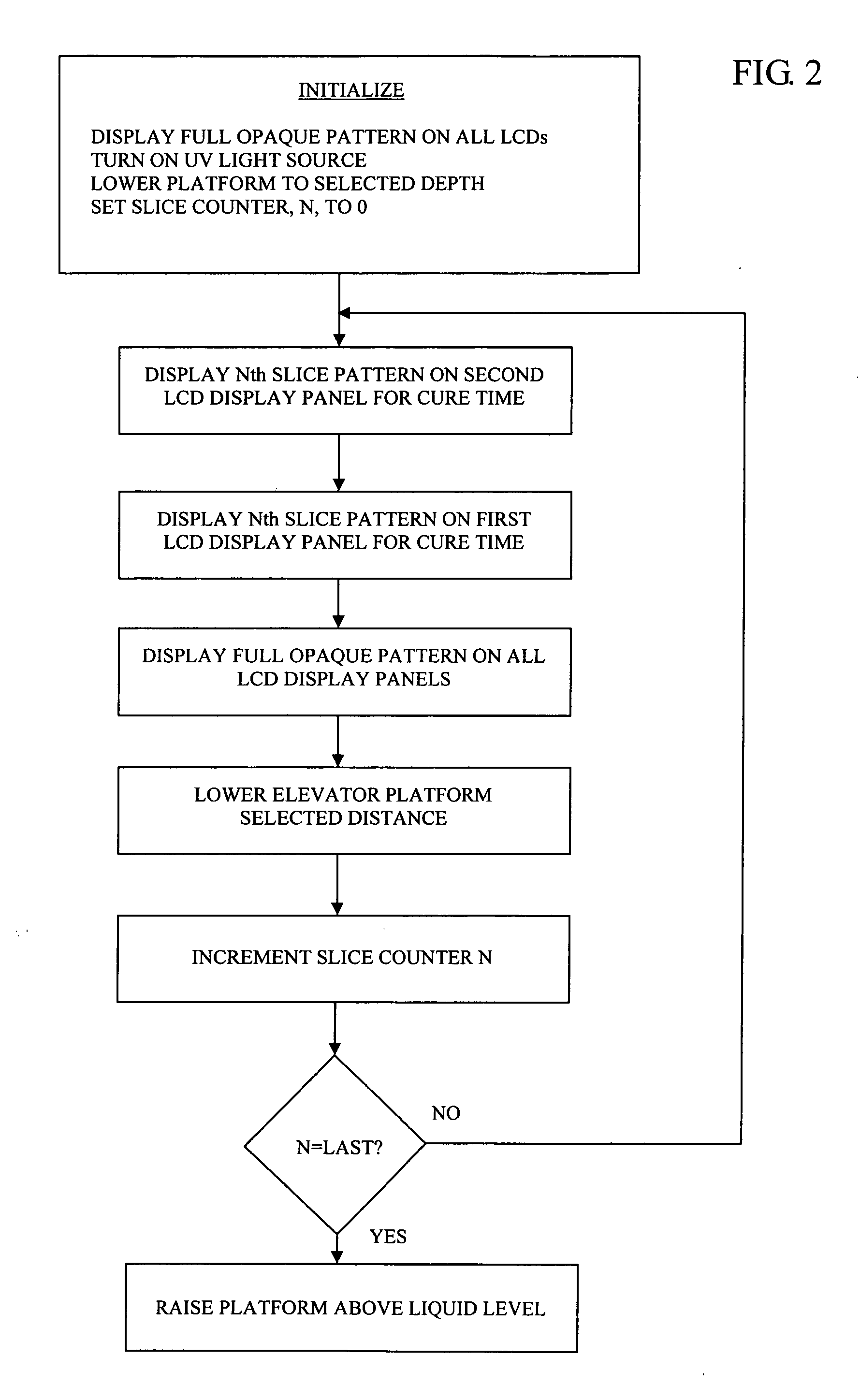
An improved rapid prototyping and manufacturing system. The improvement is at least two liquid crystal display panels interposed between a UV light source and a descendible platform to form a variably programmable photomask. A computer is connected to each display panel and includes stored, sliced data sets representing parallel, cross-sectional patterns of an object at spaced increments. The platform is lowered, preferably in stepwise increments, and selected patterns are sequentially displayed on each LCD panel as bitmaps generated from the sliced data sets to provide a series of photomasks, each photomask representing a parallel cross-section of the object at spaced increments. Preferably, an entirely opaque display pattern is displayed on the each panel during the time intervals of platform motion and one of the display panels is switched from an entirely opaque display pattern to a pattern representing a parallel, cross-section at least one liquid crystal phase cycle before the other panel is switched.

Description

BACKGROUND OF THE INVENTION [0001] 1. Field of the Invention [0002] This invention relates generally to systems for rapid prototyping and manufacturing of objects using photocurable polymer and more particularly to such systems having a considerably reduced cost of both the equipment and the materials consumed in the fabrication of the objects. [0003] 2. Description of the Related Art [0004] The prior art has developed an extensive variety of rapid prototyping and manufacturing systems for the computer aided manufacture of three-dimensional objects such as models of mechanical component parts. Most of these systems begin with the creation of a three-dimensional CAD data model of the object to be fabricated. The CAD software then translates the data that defines the three-dimensional object into sliced data sets representing parallel, cross-sections of the object which are spaced at a desired increment. In some systems, a perforated, elevator platform is immersed in a vat of a photoc...

Claims


Application Information

Patent Timeline
IPC IPC(8): G06F19/00
CPCA61C13/0004B29C67/0066B29C67/007G05B19/4099B29C64/135B29C64/129B29C64/386
Inventor SIMONIS, STEVEN F.
Owner SIMONIS STEVEN F
Learn More