Apparatus and method for irradiating electron beam

a technology of electron beam and electron beam, which is applied in the direction of optical radiation measurement, instruments, nuclear engineering, etc., can solve the problems of not meeting the demand for downsizing, the electron beam irradiation apparatus is extremely large in size and heavy in weight, and the widely used electron beam irradiation apparatus is extremely large in size and weight. , to achieve the effect of reducing the transmittance of an electron beam, reducing the adverse influence of a substrate, and reducing the negativ

Inactive Publication Date: 2006-07-27
TDK CORPARATION
View PDF9 Cites 21 Cited by
  • Summary
  • Abstract
  • Description
  • Claims
  • Application Information

AI Technical Summary

Benefits of technology

[0032] In all of the aforementioned aspects, the electron beam irradiating tube is made a vacuum type, whereby a reduction in the transmittance of an electron beam is slight even at a low accelerating voltage of 80 kV or less, an electron beam can be taken out effectively, and the electron beam irradiation apparatus can be further downsized. The low accelerating voltage also makes it possible to cause an electron beam to act on a target effectively at a low depth, to reduce an adverse influence on a substrate and the amount of secondary X-rays generated, and to use stainless steel in place of harmful lead as a material for X-ray shielding.

Problems solved by technology

On the other hand, because the techniques require a large drum type irradiating tube and accelerating voltage is high, they have the following technical problems: they require strict X-ray shielding; and in order to prevent oxygen inhibition (inhibition of curing by oxygen) it is necessary to flow a large amount of inert gas such as nitrogen gas so that the concentration of oxygen in the atmosphere around a target is reduced.
Because of such technical problems, widely used electron beam irradiation apparatuses are extremely large in size and heavy in weight.
This technique, however, does not meet the demand for downsizing, because an apparatus with a load-lock camber is further enclosed in a shielding chamber made of lead.
This arrangement, however, will increase the size of the electron beam irradiation apparatus itself and reduce the advantage of downsizing the electron beam irradiation section.
In addition, a large amount of inert gas is consumed to cool down the electron beam irradiation window, so that the running cost is increased.

Method used


Image

  • Apparatus and method for irradiating electron beam
  • Apparatus and method for irradiating electron beam
  • Apparatus and method for irradiating electron beam

Examples


Embodiment Construction

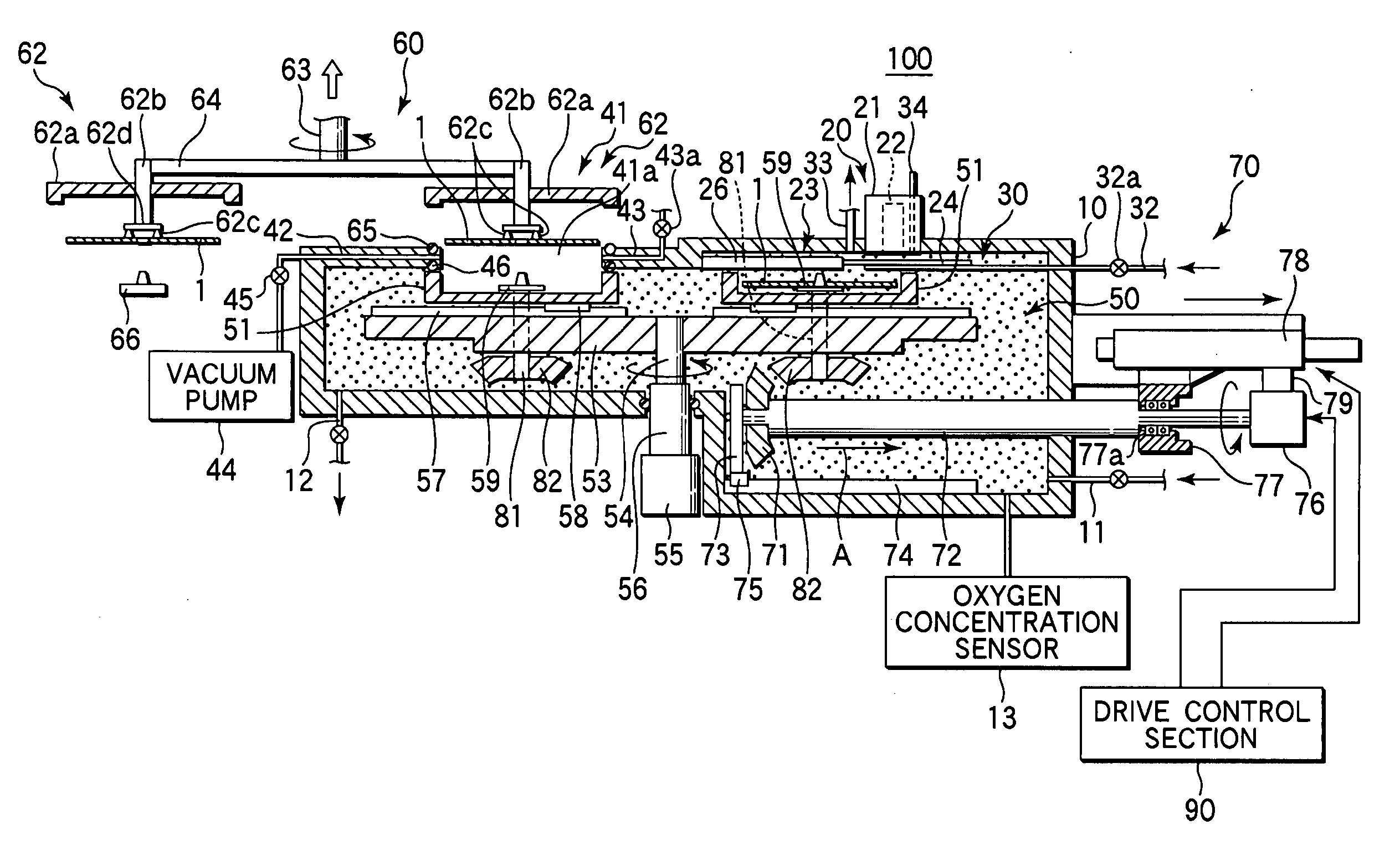
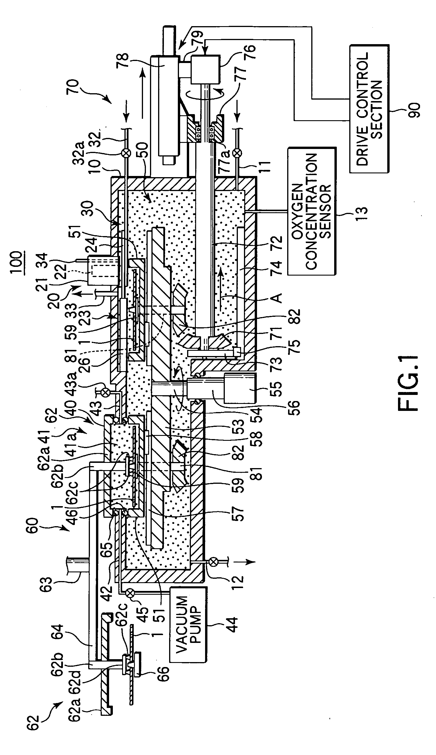
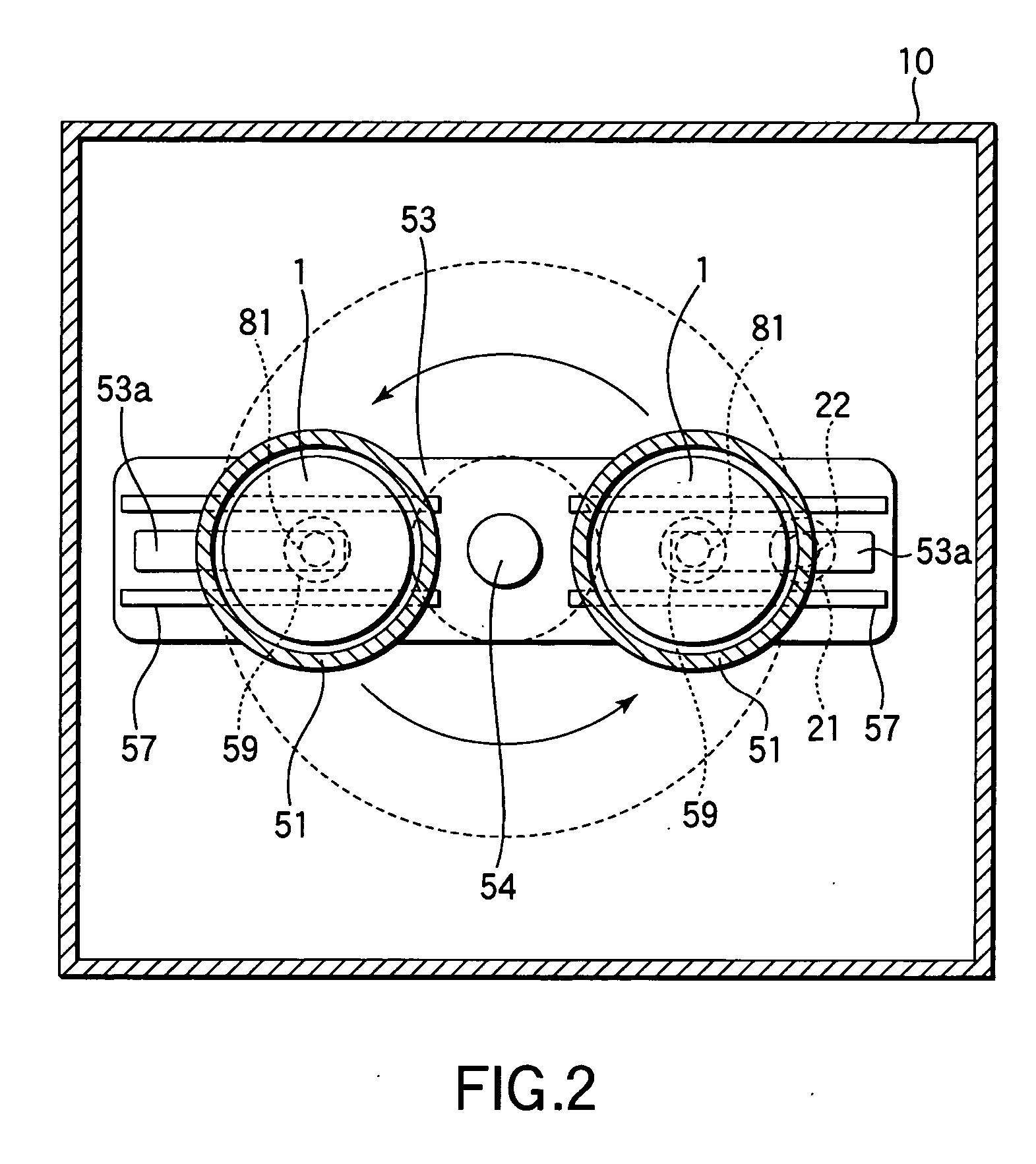
[0046] Referring now to FIGS. 1 and 2, there is shown an electron beam irradiation apparatus 100 constructed in accordance with a first embodiment of the present invention. The electron beam irradiation apparatus 100 has a chamber 10 that is a transfer container that is capable of X-ray shielding and airtight holding, and an electron beam emission section 20 mounted in the ceiling wall portion of the chamber 10. The chamber 10 contains an electron beam irradiation section 30 for irradiating an electron beam to a target 1, and a replacing chamber 40 for replacing the target 1. The electron beam irradiation apparatus 100 further has a transfer mechanism 50 for turning and transferring a target within the chamber 10; a replacement mechanism 60 for replacing a target in the replacing chamber 40; and a rotation and linear-movement section 70 for rotating and linearly moving a target in the electron beam irradiation section 30.

[0047] The transfer mechanism 50 has two support trays 51 for...


PUM

PropertyMeasurementUnit
accelerating voltageaaaaaaaaaa
angleaaaaaaaaaa
thicknessaaaaaaaaaa

Abstract

An electron beam irradiation apparatus includes an electron beam emission section having an electron beam irradiating tube that emits an electron beam; an electron beam irradiation section for irradiating the emitted electron beam to a target; a transfer mechanism for transferring the target to the electron beam irradiation section; a rotation mechanism for rotating the target on its own axis when irradiating the electron beam; and a linear movement mechanism for generating a relative linear movement such that the electron beam irradiating tube passes right above the target, between the target and the electron beam irradiating tube, when irradiating the electron beam. The linear movement mechanism generates a relative linear movement such that the electron beam irradiating tube goes from an end portion of the target toward the center of the target and turns back before the center of the electron beam emitting portion of the electron beam irradiating tube reaches the center of the target.

Description

BACKGROUND OF THE INVENTION [0001] 1. Field of the Invention [0002] The present invention relates to electron beam irradiation techniques for irradiating an electron beam to a target (such as a display unit, an optical disk, glasses, an ID card, etc.) in order to cross-link or cure a coating (such as printing ink, paint, an adhesive, a pressure sensitive adhesive, a hard protective film, etc.) formed on the target, or in order to sterilize the target or modify its properties. [0003] 2. Description of the Related Art [0004] Numerous electron beam irradiation techniques have hitherto been proposed for the cross-linking, curing, or property-modification of paint, an adhesive, a pressure sensitive adhesive, a hard protective film, etc., formed on a substrate. Such techniques are disclosed, for example, in Jpn. Pat. Appln. KOKAI Publication No. 2-208325. In the electron beam irradiation techniques, electrons are accelerated in a vacuum by an accelerating voltage, and the accelerated elec...

Claims


Application Information

Patent Timeline
Patent Type & Authority Applications(United States)
IPC IPC(8): G21K5/10G01N23/00
CPCG21K5/10
Inventor ECHIGO, NAOYUKIMARUI, YOFUSE, YOSHIHIROUSAMI, MAMORUTANAKA, KAZUSHIHIMENO, MINAOKANEKO, YUKIO
Owner TDK CORPARATION
Why Eureka
Try Eureka