Choke valve flow trim for fracture prevention

a technology for choking valves and flow trims, applied in the field of flow trims, can solve the problems of valve trim failure, significant affecting the quantity of reserves, tungsten carbide material matrix, etc., and achieve the effects of reducing flow velocity, reducing the kinetic energy contained by foreign particles, and maximizing erosion resistance and fluid handling attributes

Active Publication Date: 2006-07-27
MASTER FLO VALVE
View PDF8 Cites 9 Cited by
  • Summary
  • Abstract
  • Description
  • Claims
  • Application Information

AI Technical Summary

Benefits of technology

[0025] Preferably, the main bore or insert chamber of the choke valve is diametrically enlarged to reduce the flow velocity substantially compared to the flow velocity in the body inlet, thereby reducing the kinetic energy contained by a foreign particle.
[0026] In another broad aspect of this invention, the choke valve is modified with protuberances to maximize erosion resistance and fluid handling attributes and to further protect choke components, particularly the flow trim. In this preferred embodiment, the choke valve includes at least a pair of diametrically opposed secondary flow ports formed in the side wall of the cage, the secondary flow ports having a smaller diameter than that of the main flow ports and...

Problems solved by technology

The manner in which production reserve is produced and managed can significantly affect the quantity of the reserve.
A problem that has produced many production interruptions both with surface and subsea facilities is the failure of valve trim due to fracture.
The common causes of this fracture mechanism are foreign debris moving through the flow line into the valve with sufficient mass and velocity to damage or fracture the valve trim or the effect of liquid slugs in a high velocity gas phase entering the valve inlet.
A negative trait of the tungsten carbide material matrix is the susceptibility to fracture due to impact damage.
There have been a number of attempts at solutions to mitigate the damage caused by foreign debris; however, many of these attempts have resulted in a trade off to the potential wear capabilities of the choke trim....

Method used


Image

  • Choke valve flow trim for fracture prevention
  • Choke valve flow trim for fracture prevention
  • Choke valve flow trim for fracture prevention

Examples


Embodiment Construction

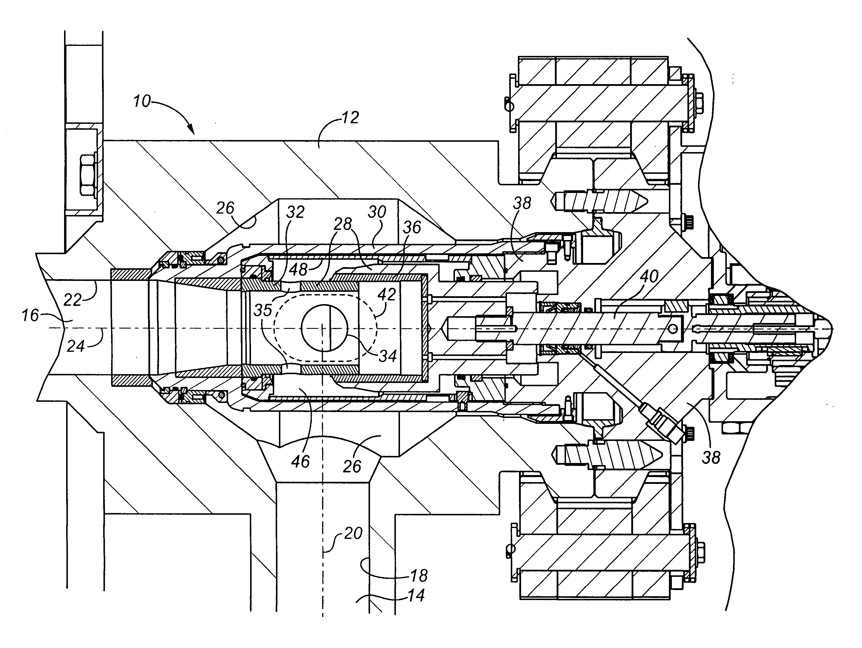
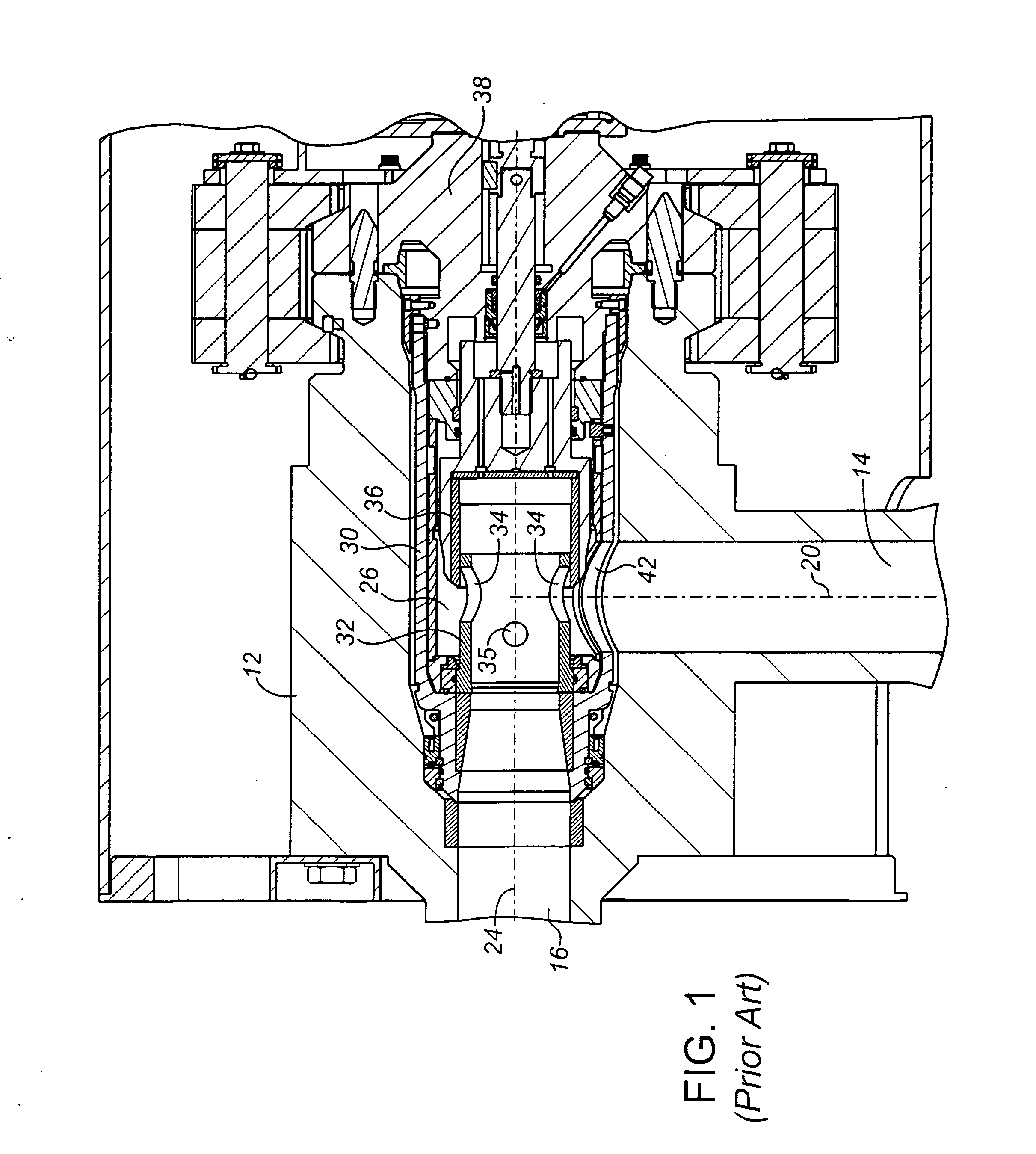
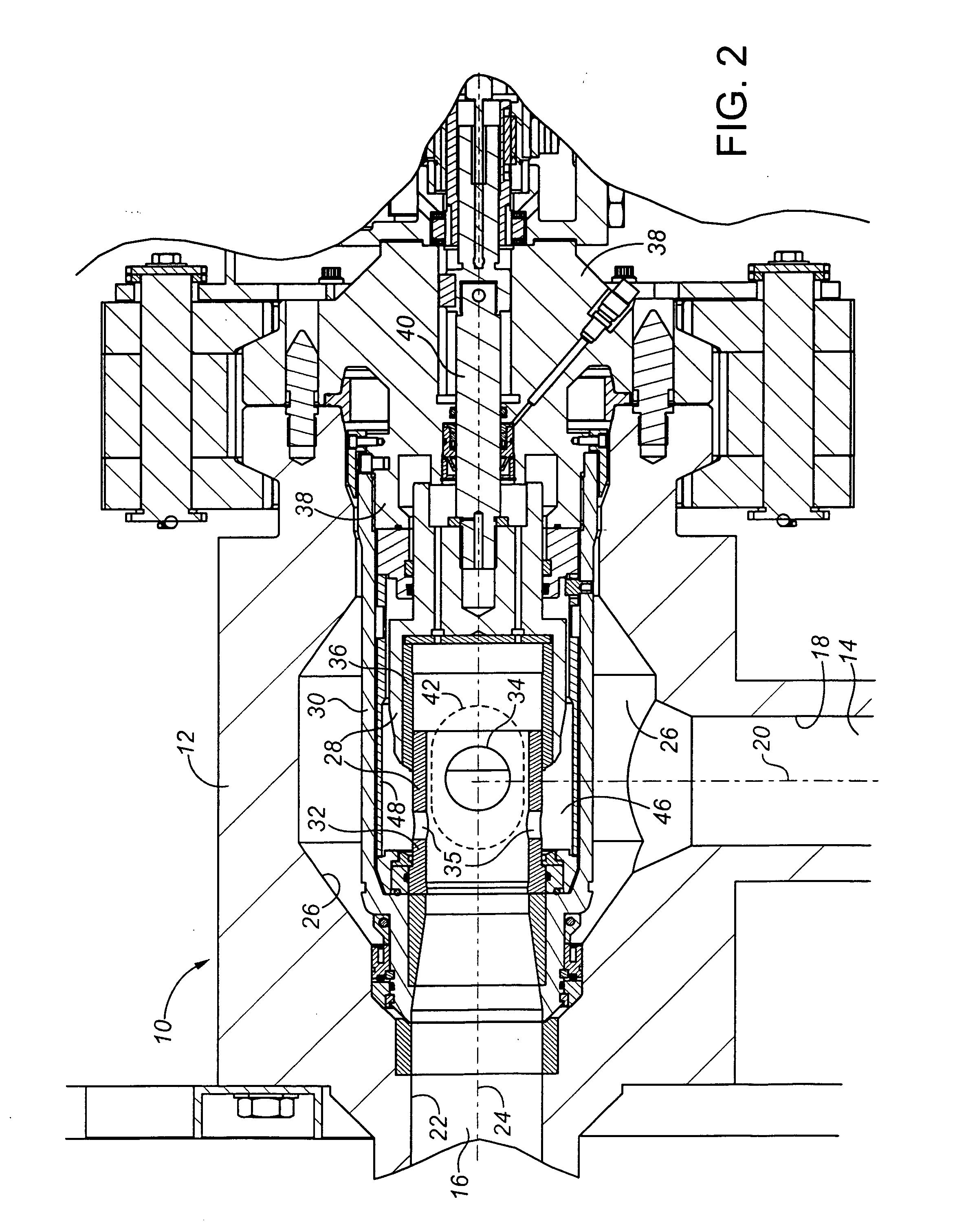
[0040] Preferred embodiments of the choke valve of the present invention are illustrated in FIGS. 2-5 to be of the internal cage, external sleeve or flow collar design, within a insert assembly such as is useful in subsea applications. To best contrast the invention, a prior art choke similar to that of U.S. Pat. No. 4,540,022 is shown in FIG. 1, with like elements being similarly numbered in all of the Figures.

[0041] Turning to FIG. 2, the choke valve of the invention is generally shown at 10 to include a hollow valve body 12, body inlet 14 and body outlet 16. The hollow valve body 12 forms a bore which extends therethrough providing side inlet bore 18 having an inlet bore axis 20, a bottom outlet bore 22 having outlet bore axis 24. The bores 18, 22 intersect at right angles (i.e., are generally T-shaped), forming a main bore 26 (also termed insert chamber) at the intersection. The main bore or insert chamber 26 is an extension of the outlet bore 22, but which also communicates wi...


PUM


Abstract

A choke valve having flow trim components, namely a tubular cage and a flow collar or plug, and related components, designed and arranged for reduced fracturing. The invention includes a protective tubular sleeve, or insert cartridge in which the side ports are located to overlap with the intersection of axes of the inlet and outlet bores, but to avoid direct impingement of fluid along the axis of the inlet bore. In the cage, at least a pair of main flow ports are located to overlap with the intersection of the axes of the inlet and outlet bores, and are aligned with the side ports of the tubular sleeve or cartridge to communicate directly with the side ports. In this manner fluid may enter the choke valve through the inlet bore and pass through the main flow ports at reduced pressure and continue out through the outlet bore, without direct impingement on the side wall of the flow trim components.

Description

CROSS REFERENCE TO RELATED APPLICATIONS [0001] This application claims priority under 35 U.S.C. 119(e) from U.S. Provisional Patent Application No. 60 / 644,670 filed Jan. 18, 2005 and U.S. Provisional Patent Application No. 60 / 715,914 filed Sep. 9, 2005. To the extent that it is consistent herewith, the aforementioned applications are incorporated herein by reference.BACKGROUND OF THE INVENTION [0002] The present invention relates to a flow trim for use in a choke valve for preventing or reducing fracturing of flow trim choke components. [0003] A choke valve is provided on the production wellhead to provide controlled production of an oil or gas reserve. By controlling the orifice through the valve, a pressure drop and flow rate is controlled to ensure the well is produced in a manner to maximize production output, meet production quotas, minimize sand or solid production and ensure the formation is not damaged through the process. The manner in which production reserve is produced a...

Claims


Application Information

Patent Timeline
IPC IPC(8): F16K31/00
CPCE21B34/02F16K3/24F16K47/08Y10T137/86759E21B34/025
Inventor BOHAYCHUK, LARRY J.KOWALCHUK, LORENRABBY, PATRICKDANNISH, CHAD
Owner MASTER FLO VALVE
Why Eureka
Try Eureka