Direct RF complex analog to digital converter

a converter and complex technology, applied in the field of digital communication systems, can solve the problems of time delay between each of these m clocks, and achieve the effects of less weight, less cost, and increased system reliability

Inactive Publication Date: 2006-07-27
LOCKHEED MARTIN CORP
View PDF2 Cites 22 Cited by
  • Summary
  • Abstract
  • Description
  • Claims
  • Application Information

AI Technical Summary

Benefits of technology

[0011] The present invention addresses the needs and concerns described above. The present invention provides a single-chip device, or group of devices, that directly samples and converts RF signals to baseband without the use of the analog circuitry normally used to mix RF signals prior to A to D conversion. This device filters, demodulates, and converts RF signals into a digital format, without the use of mixer or local oscillator circuitry. Accordingly, radar syst...

Problems solved by technology

The time delay between each of these M clocks however,...

Method used


Image

  • Direct RF complex analog to digital converter
  • Direct RF complex analog to digital converter
  • Direct RF complex analog to digital converter

Examples


first embodiment

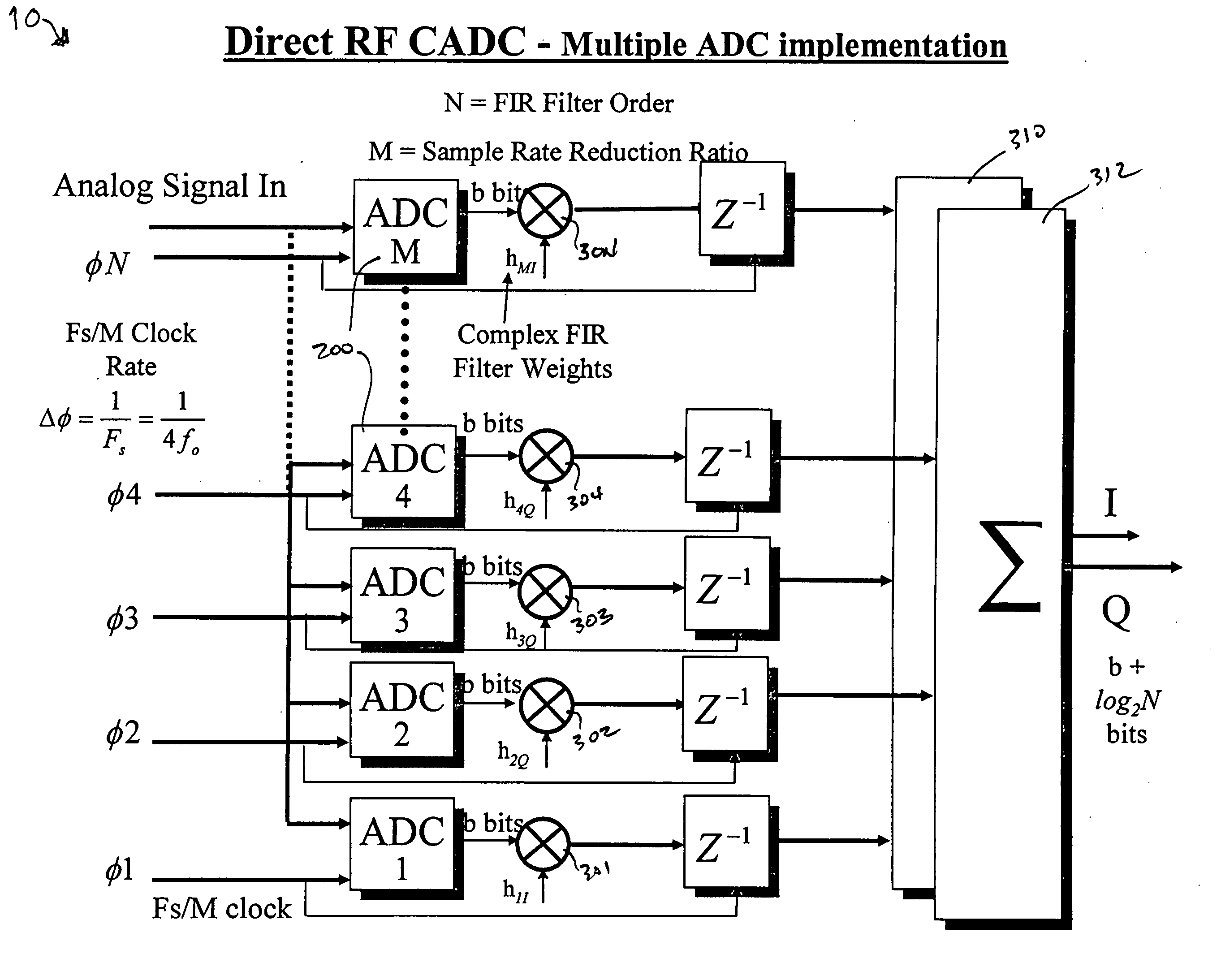
[0059] As embodied herein and depicted in FIG. 6, a block diagram of a direct RF complex analog-to-digital converter (CADC) 10 in accordance with the present invention is disclosed. CADC 10 includes rate reduction system 20, which is comprised of N low speed analog to digital converters (ADCs) 200, N being an integer number. Each ADC is coupled to register 202. Each register 202 is coupled to an in-phase multiplier (301-I . . . 30N-I) and a quadrature multiplier (301-Q . . . 30N-Q). The digital values are multiplied by a complex filter weight as given by equation (1). The digital sample equals “b” bits of sampled data, “b” being an integer number. Typically, “b” is 8 bits or greater, but depends upon the state-of-the-art and the sampling rate. In-phase multipliers 301-I . . . 30N-I are coupled to summer circuit 310. Quadrature multipliers 301-Q . . . 30N-Q are coupled to summer circuit 312.

[0060] The device of FIG. 6 operates as follows. The carrier frequency fo of the RF is typical...

second embodiment

[0066] As embodied herein and depicted in FIG. 10, a block diagram of a direct RF complex analog-to-digital converter (CADC) in accordance with the present invention is disclosed. In this embodiment, the low speed ADCs are replaced by sample and hold circuits 230. The timing of the sample and hold circuits is identical to the timing employed by the low speed ADCs shown in FIG. 6 and FIG. 7. On the other hand, sample and hold circuits 230 do not provide a digital output word. The sample and hold circuit merely samples the amplitude of the RF signal when enabled by its corresponding phase clock. Subsequently, the sampled analog output is multiplied by a complex coefficient value stored in the weighting circuits 330, 332. Weighting circuit 330 provides in-phase analog signal samples and weighting circuit 332 provides quadrature analog signal values. The in-phase signals are summed by summer circuit 340. The quadrature signals are likewise summed by summer circuit 342. The summed analog...


PUM


Abstract

An analog to digital converter device that includes a sample rate reduction system configured to sample a radio frequency (RF) signal. The RF signal has a bandwidth centered at a first frequency. The sample rate reduction system is configured to directly sample the RF signal at a sampling rate that is an integer multiple of the first frequency. The sample rate reduction system also is configured to provide M-sample outputs, each of the M-sample outputs being sampled at a reduced sampling rate equal to the sampling rate divided by M. M is an integer sample rate reduction value. An Nth order complex bandpass filter is coupled to the sample rate reduction system. The complex bandpass filter is configured to filter each of the M-sample outputs to obtain a plurality of complex baseband signals.

Description

BACKGROUND OF THE INVENTION [0001] 1. Field of the Invention [0002] The present invention relates generally to communication systems, and particularly to digital communication systems. [0003] 2. Technical Background [0004] Operations on real signals, such as RF signals, are usually concerned with only the amplitude and phase characteristics of the signal, and not with the information about the carrier signal. In other words, these operations are only concerned with the complex envelope of the signal. Accordingly, a primary objective in signal processing is to extract the complex envelope from the real signal. The complex envelope of the signal of interest may be obtained from the analytic signal via demodulation. As those of ordinary skill in the art will appreciate, the analytic signal is simply the positive frequency component of the real signal. The complex envelope is extracted from the real signal by demodulating the signal to baseband and low-pass filtering the resultant baseb...

Claims


Application Information

Patent Timeline
IPC IPC(8): H04L27/22
CPCH04L27/3845
Inventor TIETJEN, BYRON W.
Owner LOCKHEED MARTIN CORP
Why Eureka
Try Eureka