Variable displacement compressor

a compressor and variable displacement technology, applied in the direction of positive displacement liquid engines, machines/engines, mechanical equipment, etc., can solve the problems of self-induced oscillation of the suction valve, difficult to and generating noise, so as to achieve favorable starting performance and suppress the gas pressure variation. reliability

Inactive Publication Date: 2006-07-27
TOYOTA IND CORP
View PDF10 Cites 26 Cited by
  • Summary
  • Abstract
  • Description
  • Claims
  • Application Information

AI Technical Summary

Benefits of technology

[0006] Accordingly, it is an objective of the present invention to provide a variable displacement compressor that reliably suppresses variation of gas pressure when varying the displacement, while maintaining favorable starting performance of the compressor.

Problems solved by technology

This may cause self-induced oscillation of the suction valve in a free oscillation area in which the suction valve is prevented from contacting a stopper.
The pressure variation of the gas then transmits to an evaporator of an external refrigerant circuit connected to the compressor, thus generating noise.
This may destabilize the operation of the open degree control valve, making it difficult to suppress the pressure variation of the gas.
This may lead to evaporation of an excessive amount of liquid refrigerant in the crank chamber.
The pressure in the crank chamber thus rises excessively.
As a result, the displacement of the compressor reaches a sufficiently high level only with a relatively long delay, hampering the starting performance of the compressor.

Method used


Image

  • Variable displacement compressor
  • Variable displacement compressor
  • Variable displacement compressor

Examples


Embodiment Construction

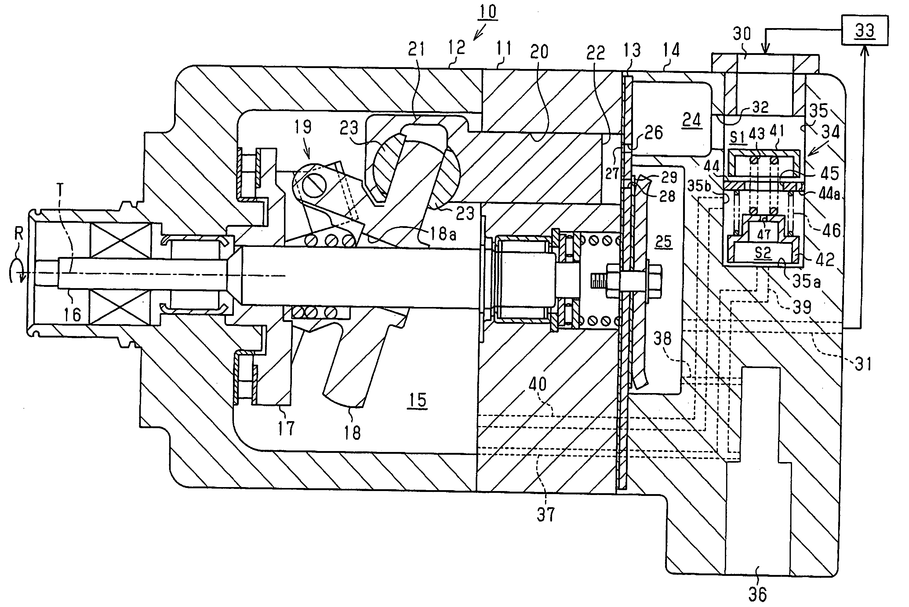
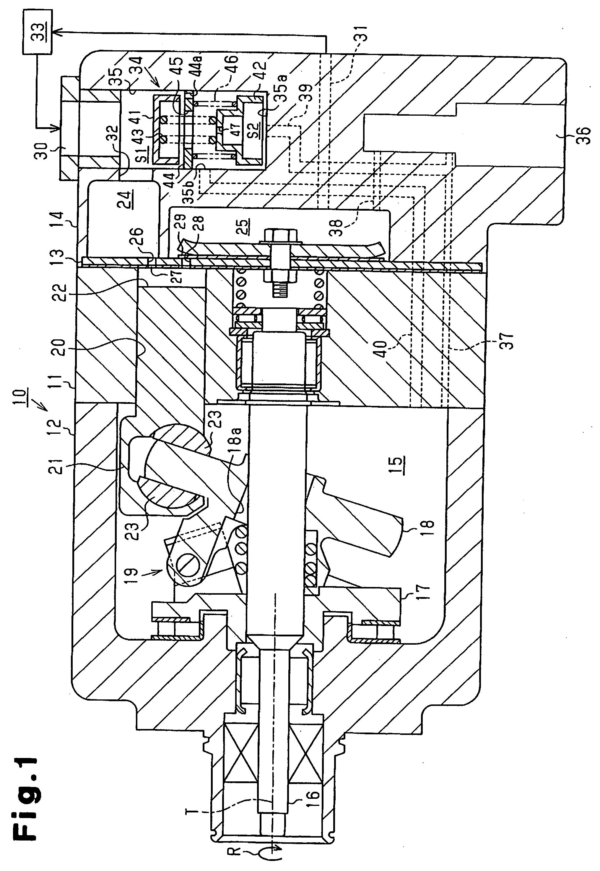
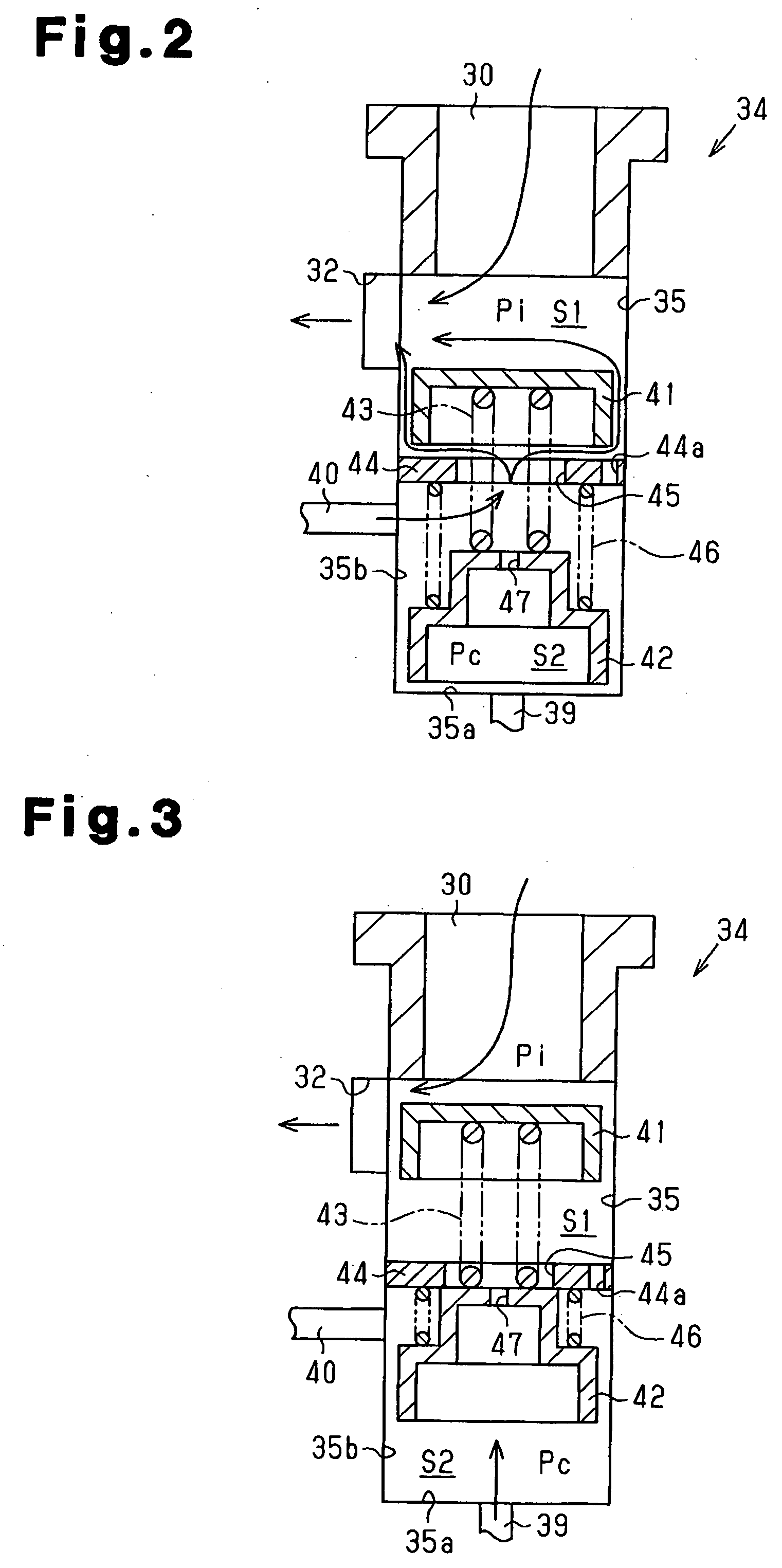
[0013] A clutch less type variable displacement compressor according to an embodiment of the present invention will now be described with reference to FIGS. 1 to 3.

[0014]FIG. 1 is a longitudinal cross-sectional view showing a compressor 10 of the illustrated embodiment. A front portion of the compressor 10 is illustrated in a left part of FIG. 1 and a rear portion of the compressor 10 is illustrated in a right part of the drawing. As shown in FIG. 1, the compressor 10 includes a cylinder block 11, a front housing member 12, a valve housing member 13, and a rear housing member 14. The front housing member 12 is securely joined with the front end of the cylinder block 11. The rear housing member 14 is securely joined with the rear end of the cylinder block 11. The valve housing member 13 is arranged between the cylinder block 11 and the rear housing member 14. The housing of the compressor 10 is defined by the cylinder block 11, the front housing member 12 and the rear housing member...


PUM


Abstract

Refrigerant gas is introduced into a suction chamber through a suction line. Refrigerant gas is allowed to flow from the crank chamber into the suction chamber through an outlet line. An open degree adjustment valve (34) has a first valve body for adjusting an open degree of the suction line and a second valve body for adjusting an open degree of the outlet line. The first valve body and the second valve body are connected to each other. The first valve body moves in such a manner as to increase the open degree of the suction line when the difference between the pressure in the suction chamber and the pressure in the crank chamber decreases, and reduce the open degree of the suction line when the difference between the pressure in the suction chamber and the pressure in the crank chamber increases. Thus, variation of gas pressure is reliably suppressed while maintaining favorable starting performance of the compressor.

Description

BACKGROUND OF THE INVENTION [0001] The present invention relates to variable displacement compressors that vary the stroke of a piston accommodated in a cylinder bore by adjusting the pressure in a crank chamber. [0002] A variable displacement compressor allows a piston to reciprocate in a cylinder bore through rotation of a drive shaft. This compresses the gas in a compression chamber and thus discharges the gas from the compression chamber. The displacement of the compressor is varied by varying the stroke of the piston. When the gas flow rate of the compressor is relatively low, the amount of the gas passing through a suction valve correspondingly decreases. This may cause self-induced oscillation of the suction valve in a free oscillation area in which the suction valve is prevented from contacting a stopper. Such oscillation of the suction valve may vary the pressure of the gas. The pressure variation of the gas then transmits to an evaporator of an external refrigerant circuit...

Claims


Application Information

Patent Timeline
Patent Type & Authority Applications(United States)
IPC IPC(8): F04B1/26
CPCF04B27/1804F04B49/225F04B2027/1831F04B2027/1845F04B2027/1859F04B2027/1881F04B27/1018F04B27/1036F05B2210/12F05B2210/14Y10S417/00
Inventor OTA, MASAKINAKAYAMA, OSAMUKANAI, AKINOBUYAMANOUCHI, AKIHITO
Owner TOYOTA IND CORP
Why Eureka
Try Eureka