
Method and apparatus for an exhaust emissions control system

Inactive Publication Date: 2006-08-03
ROBERT BOSCH GMBH
View PDF6 Cites 31 Cited by
  • Summary
  • Abstract
  • Description
  • Claims
  • Application Information

AI Technical Summary

Benefits of technology

[0012] As operation of the exhaust emissions control system proceeds, provision is made in a preferred embodiment for the adaptation of the delivery module and metering module to be accomplished as necessary and / or cyclically at specific time intervals. A recalibration as necessary may be required, for example, if an elevated nitrogen oxide content is detected with a sensor in the exhaust section. This allows a long-term and reliable reduction in nitrogen oxides from the exhaust gas during continuous operation. Any drift of the optimum working point as a result of aging of the components can thereby be compensated for.
[0014] An object relevant to the apparatus is achieved in that the value of a reference pressure based on the pressure forming in the exhaust gas conduit in the context of a calibration cycle is stored in the control module, with the result that a calculation of the optimum working point, and thus an optimum adaptation of the delivery and metering modules, can be effected.

Problems solved by technology

This complicates the process of compensating for production tolerances, which was previously still possible by applying a corresponding characteristic curve in the control unit.
For logistical reasons, this can be accomplished only with greater effort.

Method used


Image

  • Method and apparatus for an exhaust emissions control system
  • Method and apparatus for an exhaust emissions control system

Examples


Embodiment Construction

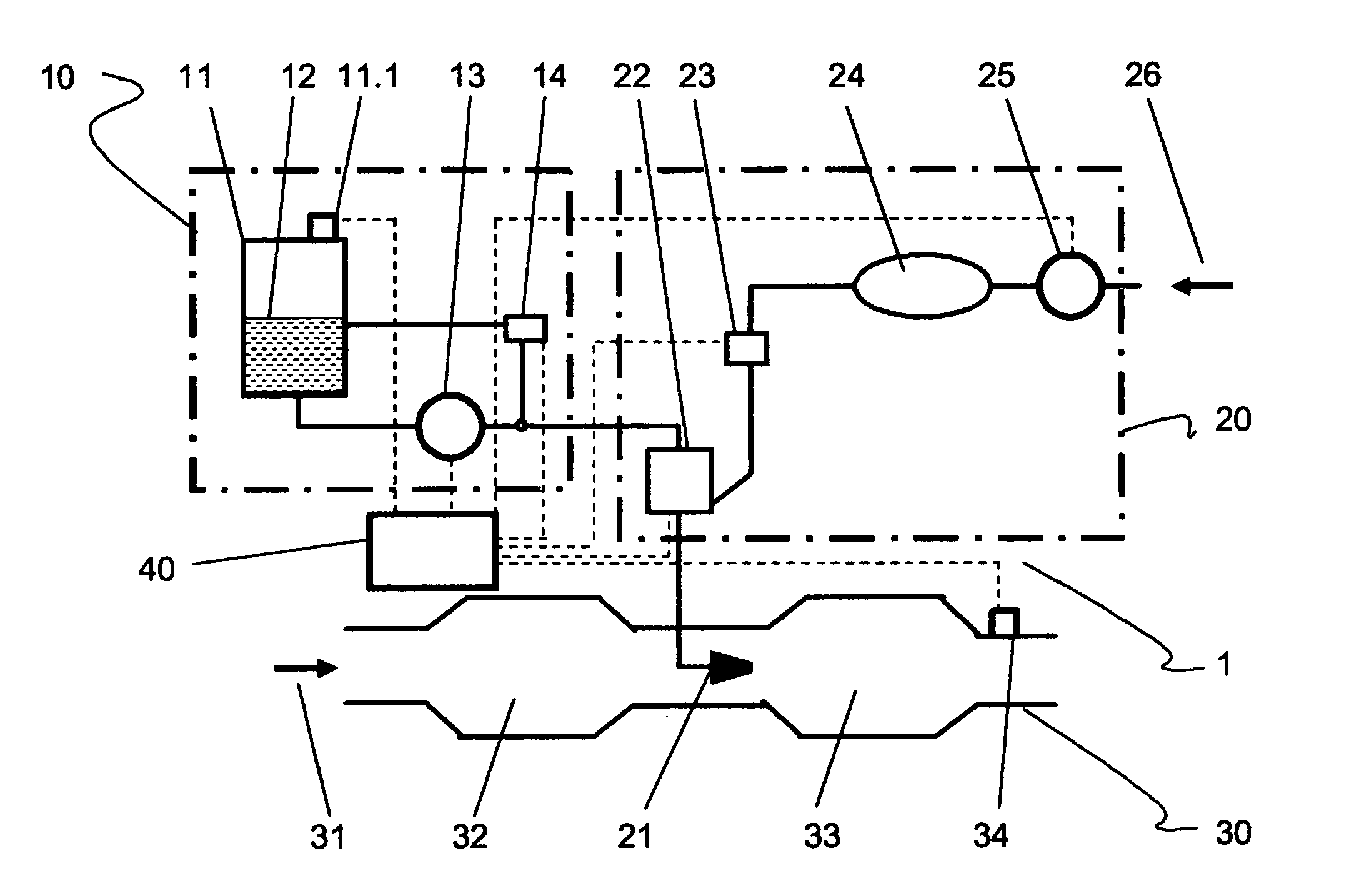
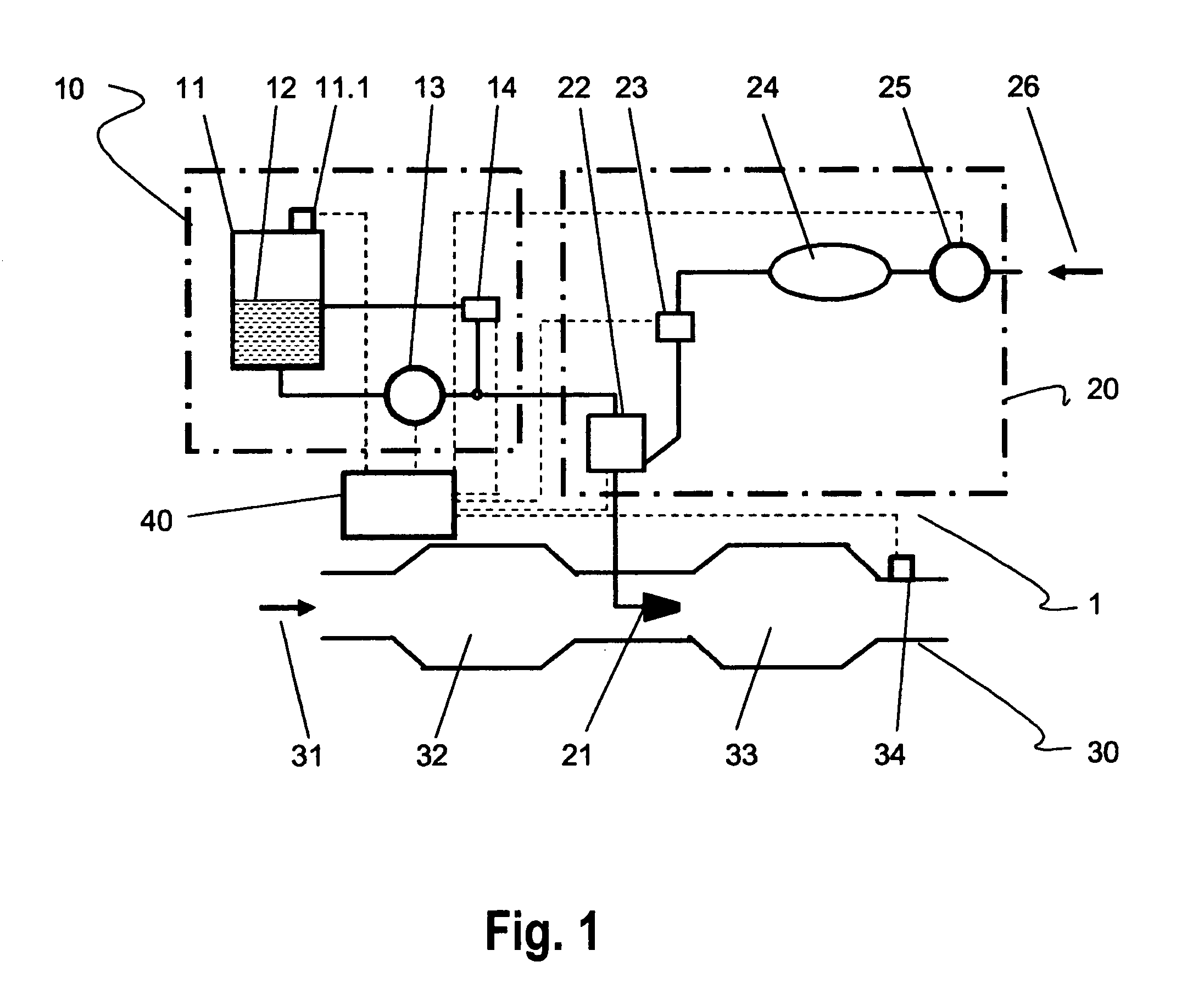
[0017]FIG. 1 shows a delivery module 10 and a metering module 20 of an exhaust emissions control system according to the existing art, having an exhaust gas conduit 30 and a control module 40.

[0018] Delivery module 10 is made up of a reservoir 11 that has a venting valve 11.1 and contains a uric acid solution (UWS) 12 which is conveyed via a delivery pump 13 to a metering valve 22. A pressure regulating valve 14 connected to the delivery side of pump 13 opens when the system pressure is too high, and then returns UWS to reservoir 11. In metering module 20, an air stream 26 is compressed with the aid of a pump 25, conveyed to a pressure accumulator 24, and conveyed via a regulating valve 23, together with the uric acid solution from delivery pump 13, to a metering valve 22. From there the air / UWS mixture is conveyed to an atomizer unit 21 disposed in exhaust gas conduit 30. In exhaust gas conduit 30, an exhaust gas stream 31 is conveyed in a first chamber to an oxidation catalytic c...


PUM

PropertyMeasurementUnit
Pressureaaaaaaaaaa

Abstract

A method for mutual adaptation of a delivery module and a metering module of an exhaust emissions control system that has an exhaust gas conduit and a control module, the delivery module having a reservoir that has a venting valve and contains a uric acid solution that is conveyed via a delivery pump to a pressure regulating valve; and in the metering module, an air stream being compressed with the aid of a pump, conveyed to a pressure accumulator, and conveyed via a regulating valve, together with the uric acid solution, out of the pressure regulating valve to a metering valve, and being conveyed from there to an atomizer unit disposed in the exhaust gas conduit, the value of a reference pressure based on the pressure forming in the exhaust gas conduit being stored in the control module. A method for mutual adaptation of a delivery module and a metering module of an exhaust emissions control system having a control module, a respective parameter or characteristic curve being created for the delivery module and for the metering module and being introduced into the respective module as a machine-readable code. An apparatus for mutual adaptation of a delivery module and metering module for an exhaust emissions control system having an exhaust gas conduit and a control module, the value of a reference pressure based on the pressure forming in the exhaust gas conduit in the context of a calibration cycle being stored in the control module. A mutual adaptation of any arbitrary metering and delivery modules can thereby be implemented in a simple and economical fashion.

Description

FIELD OF THE INVENTION [0001] The present invention relates to a method for mutual adaptation of a delivery module and a metering module of an exhaust emissions control system that has an exhaust gas conduit and a control module, the delivery module having a reservoir that has a venting valve and contains a uric acid solution that is conveyed via a delivery pump to a pressure regulating valve; and in the metering module, an air stream being compressed with the aid a pump, conveyed to a pressure accumulator, and conveyed via a regulating valve, together with the uric acid solution, out of the pressure regulating valve to a metering valve, and being conveyed from there to an atomizer unit disposed in the exhaust gas conduit. [0002] The present invention further relates to an apparatus for mutual adaptation of a delivery module and metering module for an exhaust emissions control system having an exhaust gas conduit and a control module. BACKGROUND INFORMATION [0003] Appropriate exhaus...

Claims


Application Information

Patent Timeline
IPC IPC(8): F01N3/00
CPCB01D53/90B01D53/9431B01D2251/2067F01N3/208F01N9/007F01N11/002F01N2610/02F01N2610/1466Y02T10/47Y02T10/24Y02T10/12Y02T10/40Y02A50/20
Inventor OFFENHUBER, MICHAELLACKNER, FRANZBERNEGGER, LEOPOLD
Owner ROBERT BOSCH GMBH
Learn More