Vertical type semiconductor device
a semiconductor device, vertical type technology, applied in the direction of semiconductor devices, electrical devices, transistors, etc., can solve the problem of not being able to study the effect of structure in a substantial way
- Summary
- Abstract
- Description
- Claims
- Application Information
AI Technical Summary
Benefits of technology
Problems solved by technology
Method used
Image
Examples
first embodiment
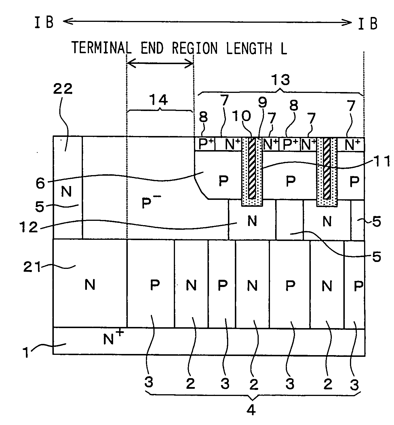
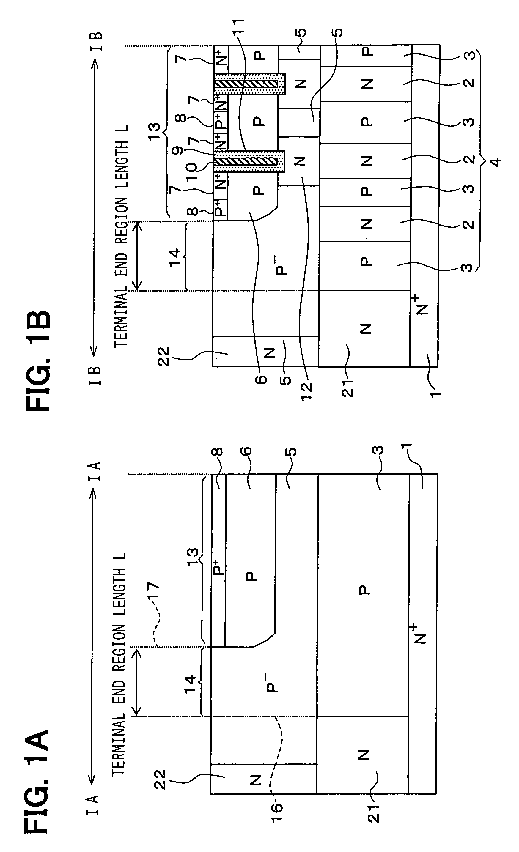
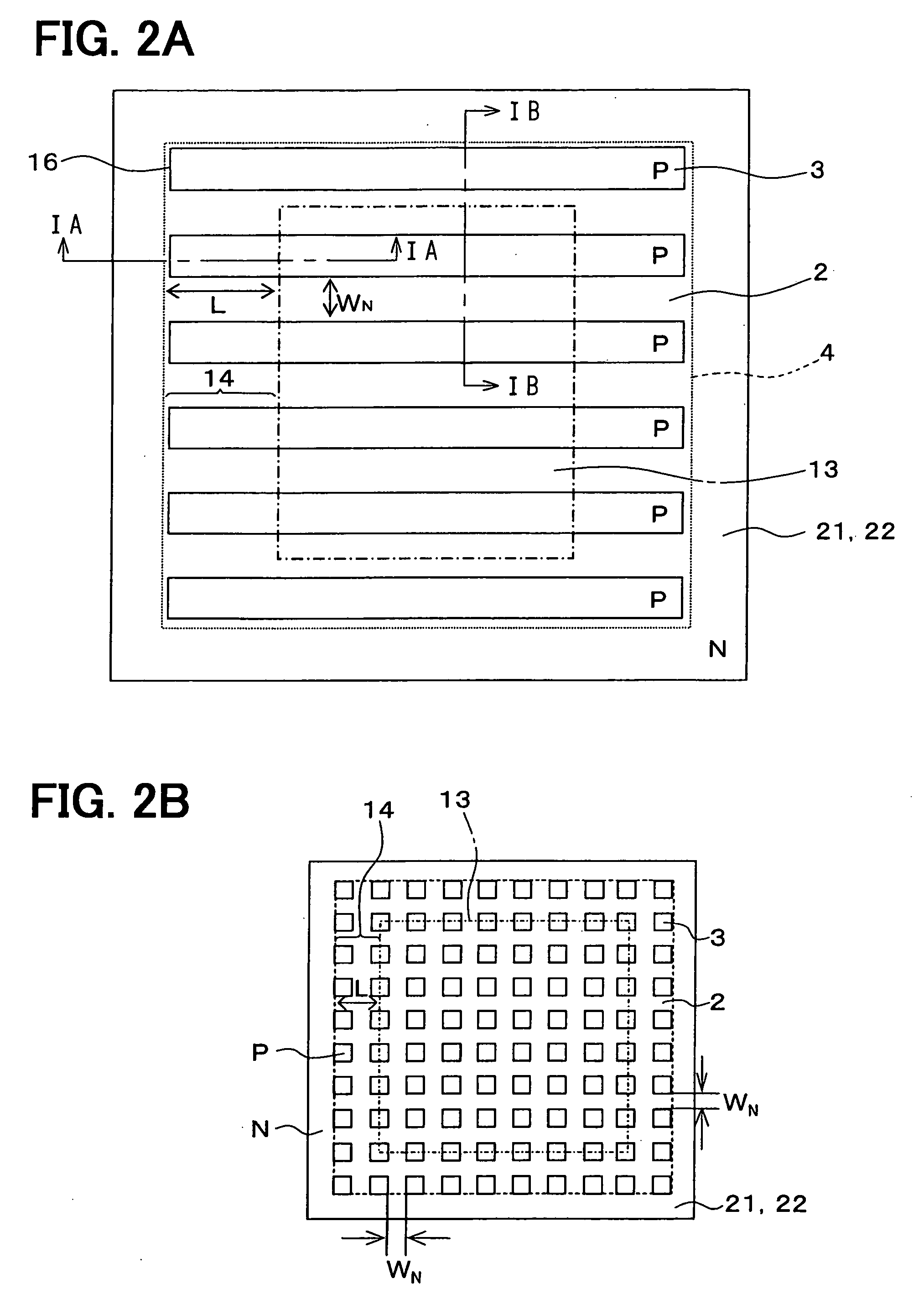
[0034]FIGS. 1A and 1B are cross sectional views showing a vertical type MOSFET according to a first embodiment of the present invention. FIG. 1A shows a structure corresponding to a IA-IA cross sectional view facing a narrow side of a P conductive type column region 3 shown in FIG. 2. To understand this embodiment easily, FIG. 1B shows a structure corresponding to a IB-IB cross sectional view facing a wide side of the P conductive type column region 3 shown in FIG. 2. This structure is known conventionally.
[0035] The vertical type MOSFET shown in the above drawings is explained. The vertical type MOSFET is formed on a semiconductor substrate having a N+ conductive type. The MOSFET includes a N+ conductive type drain region 1, a column region 4, a N+ conductive type source region 7, a P conductive type body region 6, a P+ conductive type body contact region 8 and a trench gate 11.
[0036] The N+ conductive type drain region 1 is formed from the N+ conductive type semiconductor substr...
second embodiment
[0051]FIG. 6A is a cross sectional view showing a vertical type MOSFT according to a second embodiment of the present invention. This embodiment is different from the first embodiment, the difference such that no P− conductive type semiconductor single crystal region 5 and no N conductive type buffer region 12 in the cross sectional drawing in FIGS. 1A and 1B is disposed on the substrate surface so that the column structure reaches the substrate surface, which includes no P body region 6.
[0052] The layout on the substrate surface corresponds to the IA-IA cross sectional structure facing the narrow side of the P conductive type column region 3, that is similar to the first embodiment. Here, FIG. 6B is described to understand this embodiment easily. FIG. 6B shows a structure corresponding to the IB-IB cross sectional structure facing the wide side of the P conductive column region 3 shown in FIG. 2A, the structure which is well-known conventionally.
[0053] In the second embodiment, t...
third embodiment
[0055]FIG. 7A is a cross sectional view showing a vertical type MOSFET according to a third embodiment of the present invention. FIG. 7A shows a structure corresponding to the VIIA-VIIA cross sectional structure, which faces the narrow side of the P conductive type column region 3 shown in FIG. 8. Here, FIG. 7B is described to understand this embodiment easily. FIG. 7B shows a structure corresponding to the VIIB-VIIB cross sectional structure facing the wide side of the P conductive column region 3 shown in FIG. 8, the structure which is well-known conventionally.
[0056] In the third embodiment, similar to the first embodiment, when the column structure is formed, a Si substrate having a (110)-surface is used. The column structure is formed by a wet-etching method utilizing a surface orientation dependency of an etching rate. Therefore, the shape of the column is different from that in the above described embodiments. The other fundamental structures are similar to those of the firs...
PUM
 Abstract
Description
Claims
Application Information
 - R&D
- Intellectual Property
- Life Sciences
- Materials
- Tech Scout
- Unparalleled Data Quality
- Higher Quality Content
- 60% Fewer Hallucinations
Browse by: Latest US Patents, China's latest patents, Technical Efficacy Thesaurus, Application Domain, Technology Topic, Popular Technical Reports.
© 2025 PatSnap. All rights reserved.Legal|Privacy policy|Modern Slavery Act Transparency Statement|Sitemap|About US| Contact US: help@patsnap.com


