Measuring apparatus and measuring method

a technology of measuring apparatus and measuring method, which is applied in the direction of optical measurement, optical radiation measurement, instruments, etc., can solve the problems of complex apparatus, inconvenient measurement, and increasing the sensitiveness of pattern transfer to birefringence, and achieve the effect of accurate measuremen

Inactive Publication Date: 2006-08-03
CANON KK
View PDF15 Cites 42 Cited by
  • Summary
  • Abstract
  • Description
  • Claims
  • Application Information

AI Technical Summary

Benefits of technology

[0007] It is an object of the present invention to provide a measuring apparatus and a measuring method which allow accurate measurement of birefringence of a test object over a wide area thereof.
[0017] According to the present invention, a measuring method and a measuring method can be provided which enables accurate measurement of birefringence of a test object over a wide area thereof.

Problems solved by technology

In recent years, particularly, miniaturization of devices accomplished at a fast pace has often required pattern transfer beyond a normal imaging property, and the pattern transfer is becoming sensitive to birefringence which is a polarization characteristic of an optical system.
Such an apparatus, however, can only measure birefringence at a certain point on a surface of the test object (in other words, it only can perform point measurement) since the apparatus has no image-forming system.
Thus, the apparatus is complicated and is not suitable for a test object which needs measurement over a wide area such as a projection optical system.
As a result, the apparatus is directly affected by birefringence in the diffraction grating, thereby making it impossible to measure the birefringence accurately.
It is thus difficult to eliminate the influence of the optical system (that is, the image-forming system included in the shearing interferometer) other than the test object (such as a projection optical system) in measuring a wavefront, and it is impossible to provide complete consistency between the wavefront measurement and the birefringence measurement.
In other words, the influence of the optical system included in the apparatus upon the polarization characteristic cannot be measured precisely, and the birefringence of the test object cannot be measured accurately.

Method used


Image

  • Measuring apparatus and measuring method
  • Measuring apparatus and measuring method
  • Measuring apparatus and measuring method

Examples


embodiment 1

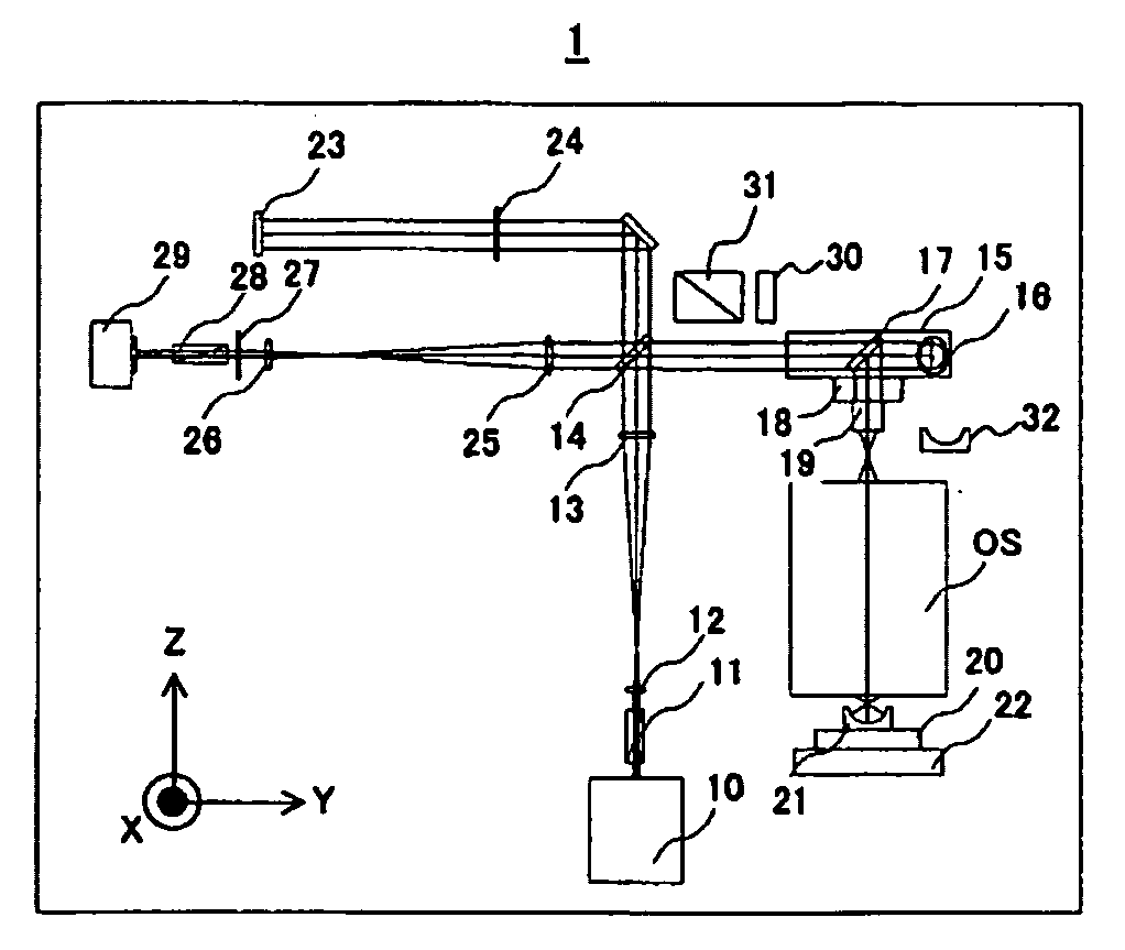
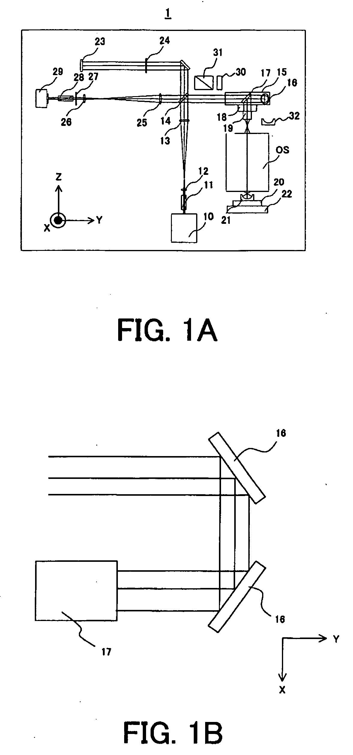
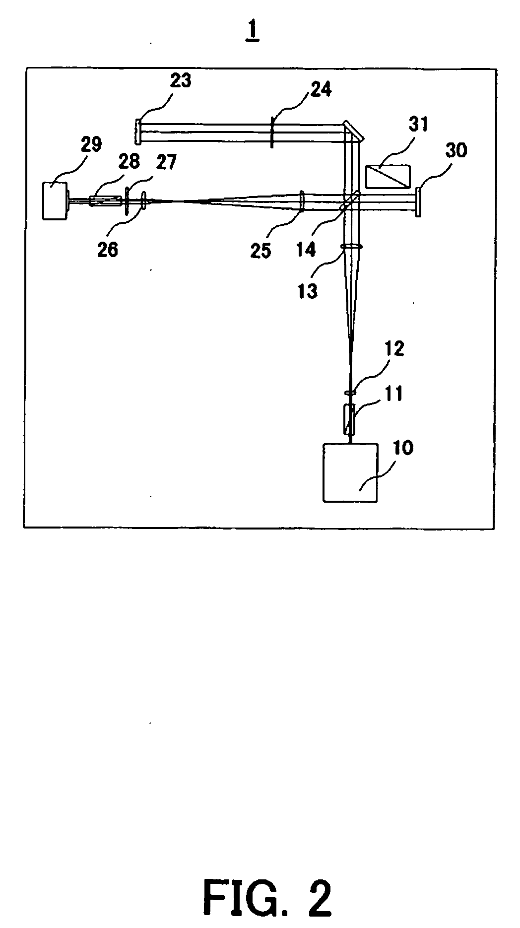
[0027]FIG. 1A is a schematic section view showing the basic structure of a measuring apparatus 1 according to an aspect of the present invention. The measuring apparatus 1 of Embodiment 1 includes a Twyman-Green interferometer for measuring a wavefront of light transmitted through a test object OS (a transmitted wavefront) and measures birefringence (a polarization characteristic) of the test object OS. In Embodiment 1, a projection optical system (a projection lens) of a projection exposure apparatus is assumed as the test object OS.

[0028] Referring to FIG. 1A, luminous flux which emitted from a light source 10 is transmitted through a polarizer 11 to have a predetermined (that is, a known) polarization state. The luminous flux emitting from the light source 10 is circularly polarized. Simply rotating the polarizer 11 about the optical axis of a measuring optical system of the measuring apparatus 1 can provide a sufficient amount of arbitrarily linearly polarized light. The measur...

embodiment 2

[0054]FIG. 4 is a schematic section view showing the structure of a measuring apparatus 1A according to an aspect of the present invention. The measuring apparatus 1A of Embodiment 2 includes a Fizeau interferometer for measuring a wavefront (a transmitted wavefront) of light transmitted through a test object OS and measures birefringence of the test object OS. Since the measurement of the Jones matrix of the test object OS associated with the measurement of the polarization characteristic matrix is similar to that in Embodiment 1, description will be made only of separation of luminous flux under test from reference luminous flux performed in a different manner from that in Embodiment 1.

[0055] Referring to FIG. 4, luminous flux which emitted from a light source 10 is linearly polarized at an arbitrary angle by a λ / 2 plate 41 and a polarizer 11. The luminous flux which emerged from the polarizer 11 is once condensed by a beam expander 12 and is reflected and diverged by a half mirr...

embodiment 3

[0064] Embodiment 3 will be described in conjunction with a method of averaging interference patterns by using fringe scan, separating luminous flux under test from reference luminous flux, and measuring a polarization characteristic matrix of a test object OS. Embodiment 1 employs the light shield plate 24 to block the reference luminous flux and Embodiment 2 employs the spatial filter 45 to block the reference luminous flux, thereby detecting only the luminous flux under test. In Embodiment 3, however, reference luminous flux is not blocked, and only the information about luminous flux under test is taken out by accumulating the intensity of interference patterns. Description will hereinafter be made mainly of the structure and operation different from those in Embodiment 2.

[0065] In Embodiment 3, in the structure of the measuring apparatus 1A shown in FIG. 4, the image-side Z stage 20 and the image-side XY stage 22 are adjusted such that the center of curvature of the spherical ...


PUM


Abstract

A measuring apparatus is disclosed which includes an interferometer for measuring a wavefront of light transmitted through a test object by interference between light under test passed through the test object and reference light, and measures a polarization characteristic of the test object. The measuring apparatus has a measuring unit for measuring a polarization characteristic matrix in a pupil plane of the test object while the reference light is blocked or fringe scan is performed.

Description

BACKGROUND OF THE INVENTION [0001] The present invention generally relates to a measuring apparatus and a measuring method, and more particularly, to a measuring apparatus and a measuring method for measuring a polarization characteristic (birefringence) of an optical system (specifically, a projection optical system) of an exposure apparatus used during a lithography process in manufacturing various devices such as a semiconductor device and a liquid crystal display device. [0002] In manufacturing very small devices with a photolithography technique, a reduced projection exposure apparatus has been used in which a projection optical system projects a circuit pattern onto a photosensitive substrate such as a wafer to transfer the circuit pattern to the photosensitive substrate. [0003] The reduced projection exposure apparatus needs to transfer a reticle pattern accurately to a wafer at a predetermined scaling factor. To satisfy the need, it is important to use a projection optical s...

Claims


Application Information

Patent Timeline
Patent Type & Authority Applications(United States)
IPC IPC(8): G01B9/02
CPCG01J4/04G01J9/02
Inventor HAYASHI, NAOTOKURAMOTO, YOSHIYUKI
Owner CANON KK
Why Eureka
Try Eureka