Sinewave inverter using hybrid regulator

a technology of inverter and regulator, applied in the field of sine wave inverter, can solve the problems of difficult regulation and prediction, complex filtering, and not being reliable at higher powers, and achieve the effects of low loss in the pass element, high efficiency, and low cos

Inactive Publication Date: 2006-08-03
PRECISIONH2
View PDF11 Cites 13 Cited by
  • Summary
  • Abstract
  • Description
  • Claims
  • Application Information

AI Technical Summary

Benefits of technology

[0017] After line regulation is obtained, a FET type linear regulation stage is added to take care of the load regulation. Due to the line-regulation, the drop across pass element is kept to a minimum and hence linear quality regulation is obtained for the fill load. At no load, the drop across the pass element increases, but current is negligible and losses in the pass element are also negligible.
[0018] Moreover, whatever the complexity of the load (inductive, capacitive, complex, abruptly varying, etc.), it does not interfere with the high frequency feedback loop or the complex impedances of the pre-regulator, avoiding a severe problem that usually exists with conventional switching regulators.
[0019] Thus, linear quality regulation (line and load) with high efficiency is made possible with this topology.
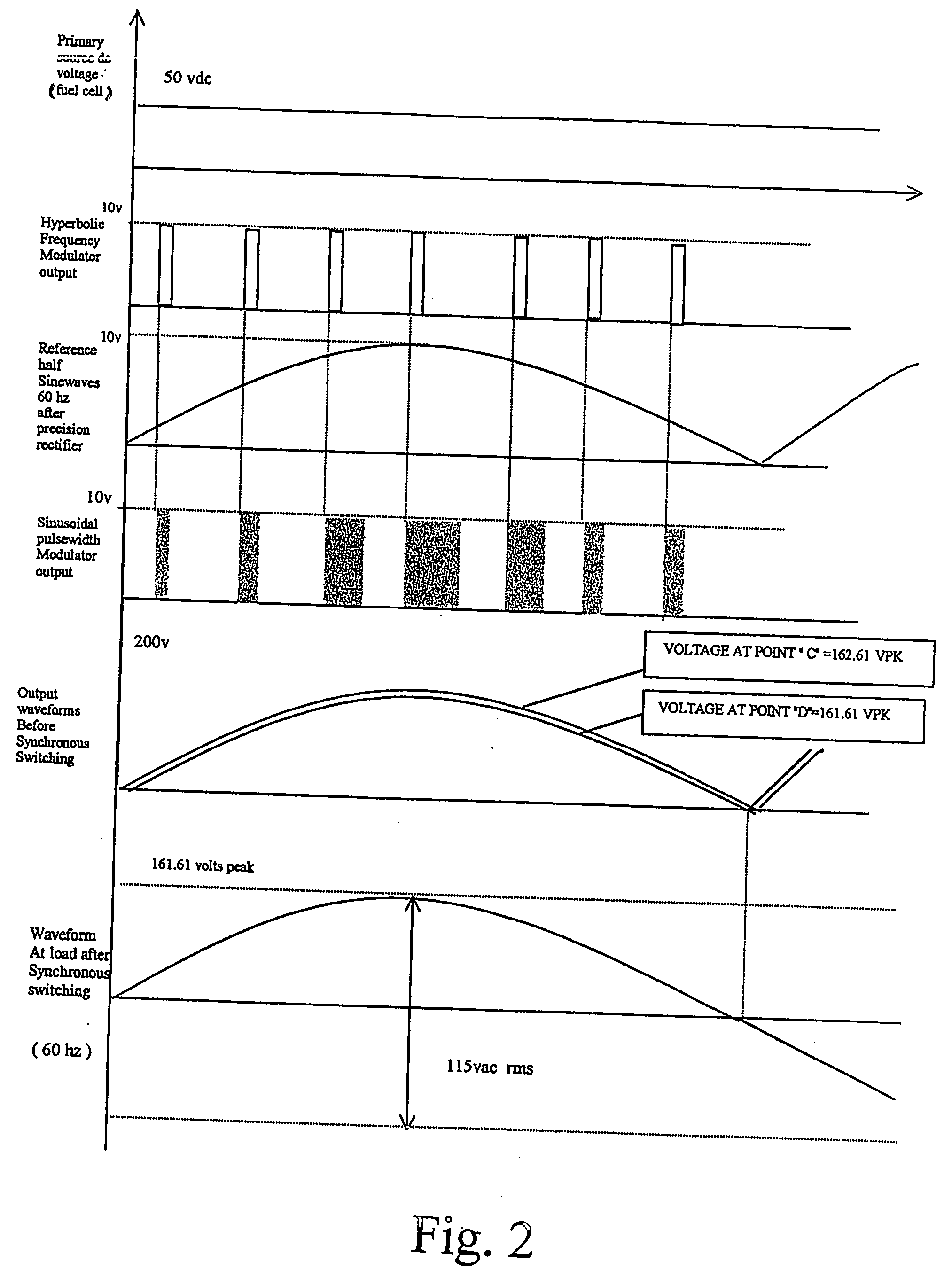
[0020] It has been surprisingly found that the converter topology described above, based on the use of 1 / x or hyperbolic frequency modulation can also produce a sinewave inverter topology that essentially complies with the five above mentioned conditions, when it is combined with a sine pulsewidth modulation. In essence, the hybrid combination of hyperbolically modulated frequency combined with sinusoidally modulated pulsewidth produces a high efficiency linearly regulated AC supply from any type of DC input.

Problems solved by technology

Such inverters were simple in nature, but due to the non-linear phenomenon appearing in the magnetic core, they were difficult to regulate and predict.
Filtering was not straightforward, because filters had to work with widely varying input and output impedances.
This approach works fairly well at low powers (below 300 watts), but becomes complicated and not too reliable at higher powers, because of the response of inductive power chokes and transformers to the sampling frequency, especially when loading is varying by large increments.
The net result of this is high development, production and maintenance costs (around $1 to $2 / watt) which amounts to $5000 to $10,000 for a 5 kw inverter.
This is not commercially viable.
At present, the above conditions cannot be achieved simultaneously, particularly in so far as the low cost is concerned for the high efficiency and other features set out above.

Method used


Image

  • Sinewave inverter using hybrid regulator
  • Sinewave inverter using hybrid regulator
  • Sinewave inverter using hybrid regulator

Examples


Embodiment Construction

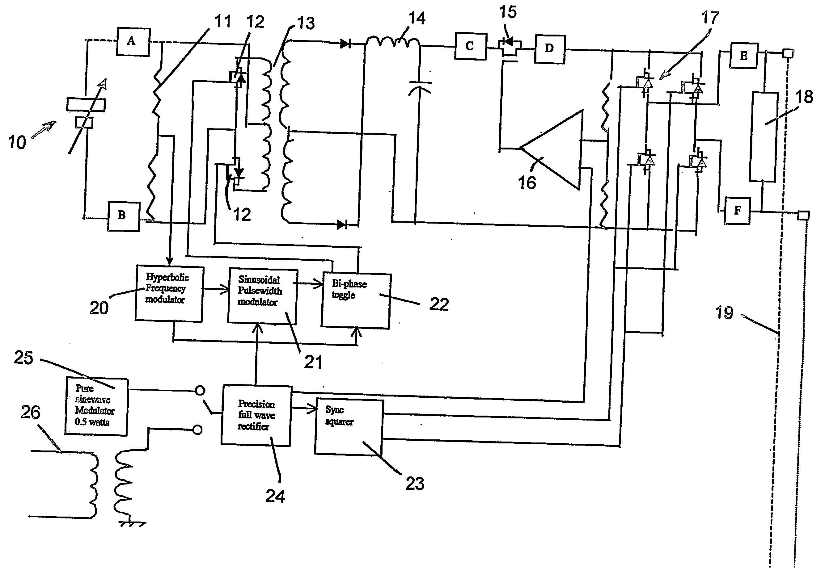
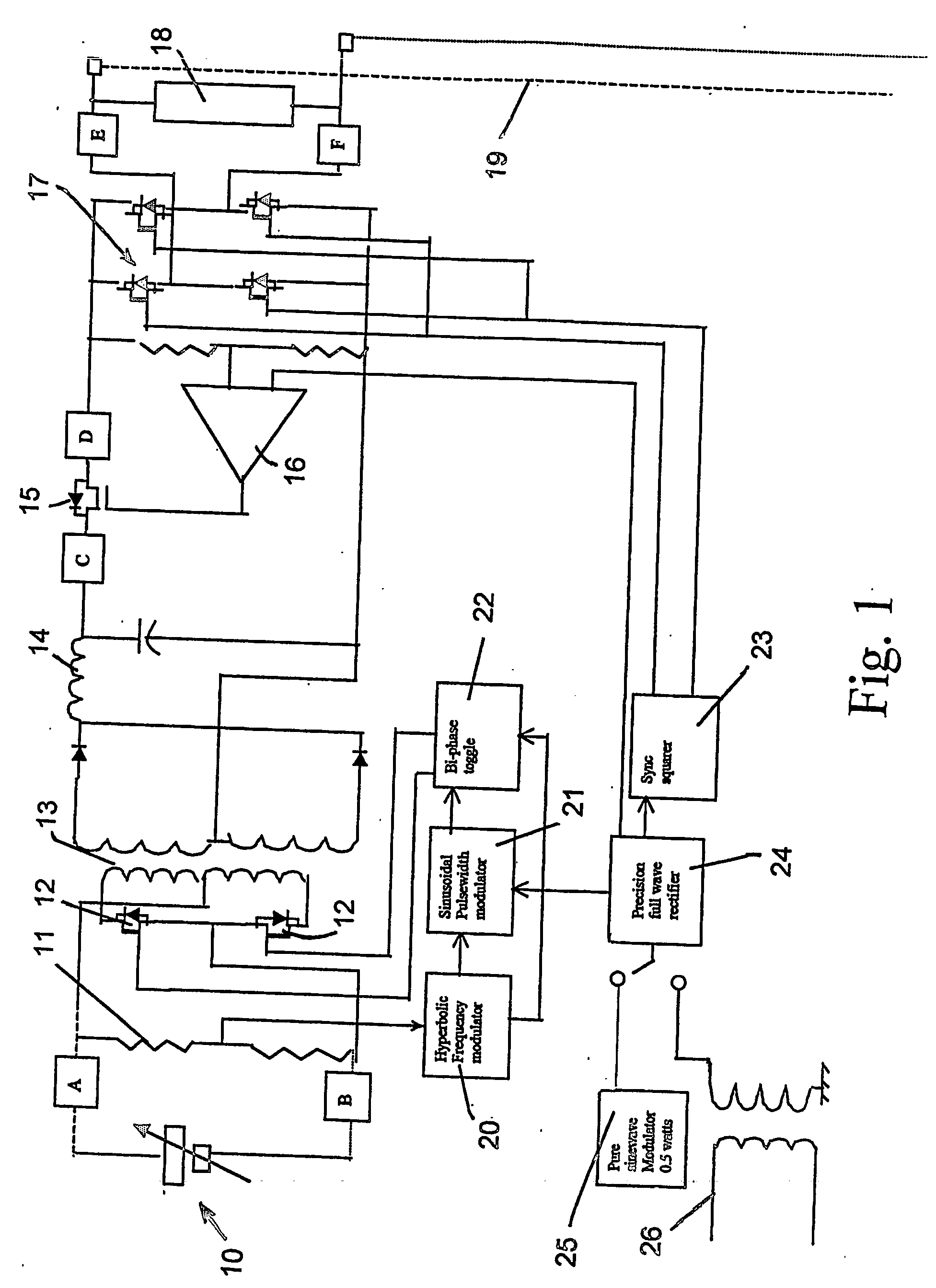
[0035] Referring to FIG. 1, it shows a block diagram representing a preferred embodiment of the inverter according to the present invention. The input 10 to the inverter is a variable DC source, such as a battery bank, fuel cell, solar cell bank and the like. DC voltage variations can be essentially limitless, but for the purposes of this embodiment, the minimum voltage is chosen to be 50 VDC and the maximum voltage 100 VDC. This unstable DC power is connected to the inverter at entry points “A” and “B”. Power out can also be any desired value, but herein it is chosen to be 115 VAC, 60 hz, 45 amps, i.e. 5 kilowatts. It is provided at exit points “E” and “F” of the inverter where the user's appliances requiring stable AC power are connected.

[0036] A voltage divider 11 is provided for feeding a fraction of the line voltage from input 10 to a hyperbolic frequency modulator 20. Two push-pull switching FETs or FET modules 12 are connected to a bi-phase toggle 22 which is a flip-flop tha...


PUM


Abstract

A sinewave inverter for converting unstable DC voltage from a variable source such as batteries, fuel cells, wind mills and the like into a distortionless sinusoidal AC voltage of constant amplitude and constant frequency is provided. This pure sinewave inverter with line and load regulated voltage is obtained by using a combination of a hyperbolic frequency modulator with a sinusoidal pulsewidth modulator in the inverter circuit.

Description

FIELD OF THE INVENTION [0001] The present invention relates to a sinewave inverter for converting DC to AC voltage, and more particularly to a kilowatts pure or distortionless sinewave inverter using a hybrid regulator comprising a hyperbolic frequency modulator combined with a sinusoidal pulsewidth modulator. BACKGROUND OF THE INVENTION [0002] DC to AC inverters appeared about 60 years ago, mainly for aerospace applications. They used various voltage mode or current mode switching techniques, such as saturating magnetic core topologies or two current sources as disclosed, for instance, in U.S. Pat. No. 4,415,962. [0003] Such inverters were simple in nature, but due to the non-linear phenomenon appearing in the magnetic core, they were difficult to regulate and predict. Filtering was not straightforward, because filters had to work with widely varying input and output impedances. [0004] With the advent of microprocessors, sampling theories with custom made software algorithmns have ...

Claims


Application Information

Patent Timeline
Patent Type & Authority Applications(United States)
IPC IPC(8): H02M7/537H02M7/538H03K7/08
CPCH02M7/53806H02M2001/0022H03K7/08H02M1/0022
Inventor CLAVEL, ROBERT
Owner PRECISIONH2
Why Eureka
Try Eureka