Hybrid amorphous metal alloy stent

a metal alloy and hybrid technology, applied in the field of stents, can solve the problems of inability to acceptably smooth, uniform surfaces of metal devices, limited fatigue resistance of current metals, etc., and achieve the effects of reducing restenosis, promoting neo-intima growth, and reducing fatigue resistan

Inactive Publication Date: 2006-08-10
MEDINOL LTD
View PDF113 Cites 82 Cited by
  • Summary
  • Abstract
  • Description
  • Claims
  • Application Information

AI Technical Summary

Benefits of technology

[0045] As a further advantage of the invention, the bioresorbable structure may be embedded with drug that will inhibit or decrease cell proliferation or will reduce restenosis in any way. Examples of such drugs include for example rapamycin and paclitaxol and analogs thereof. In addition, the stent may be treated to have active or passive surface components such as drugs that will be advantageous for the longer time after the stent is exposed by bioresorption of the longitudinal structure.
[0046] The stent may also include fenestrations. Fenestrations can be any shape desired and can be uniformly designed such as the formation of a porous material for example, or individually designed. The non-continuous layered material can also be formed in other ways such as a collection of bioresorbable fibers connecting the structure. Fenestration of the bioresorbable cover may promote faster growth of neo-intima and stabilization of the structure before degradation of the bioresorbable material. The present invention allows the bioresorbable material to be manufactured at any length and then cut in any desired length for individual functioning stents to assist manufacturing the stent. For example, in the case of bioresorbable polymer tubing, the tubing can be extruded at any length and then cut to customize the stent, either by the manufacturer or by the user.
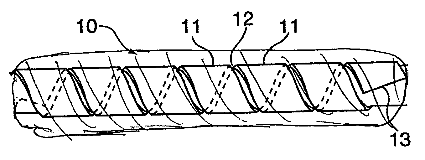
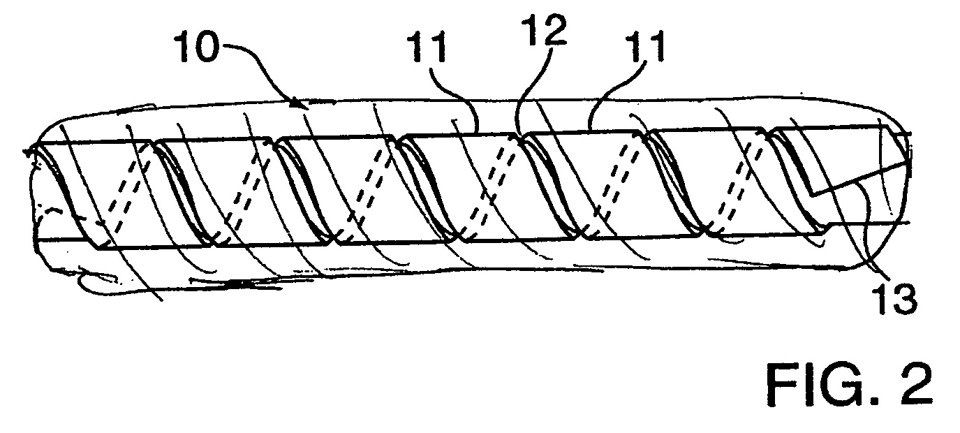
[0047] Example designs are described in, but not limited to, U.S. Pat. No. 6,723,119, which is incorporated herein in toto, by reference. One example design is the NIRflex stent which is manufactured by Medinol, Ltd. This design criteria preferably results in a structure which provide longitudinal flexibility and radial support to the stented portion of the vessel. Helically oriented strips of NIRflex cells, for example, may be manufactured and rolled into tubular amorphous metal stent structures. The tubular structure is held in position by a biocompatible material coating around the outside of the rolled tubular structure.
[0048] Another example of a flat metal stent is described in U.S. Pat. Nos. 6,503,270 and 6,355,059, which is also incorporated herein in toto, by reference. In this example, the flat metal stent design is configured as a coiled stent in which the coil is formed from a wound strip of cells wherein the sides of the cells are serpentine. Thus, the stent is made up of a strip helically wound into a series of coiled windings, wherein the strip is formed of at least two side bands connected to each other, for example by a series of cross struts. In one embodiment, each side band of the strip is formed in a serpentine pattern comprising a series of bends, wherein upon expansion of the stent, the bends of the side bands open to increase the length of each of the individual cells in the helical direction, thereby lengthening the strip in the helical direction to allow the stent to expand without any significant unwinding of the strip. The two ends of the strip at the ends of the stent are joined, for example by welding to the respective adjacent windings, thereby creating smooth ends and assuring no relative rotation. This design retains the flexibility associated with coiled spring stents, yet has windings which are relatively stable and insusceptible to displacement or tilt. A serpentine coiled ladder stent thus provides continuous support of the vessel tissue without disadvantageously obstructing the lumen.
[0049] In one embodiment of the serpentine ladder design, the stent is configured as a coiled stent in which the coil is formed from a wound strip of cells wherein the side of the cells are serpentine.
[0050] Optionally, the ends of the helical strip may be tapered. The tapering of the ends of the strip allows the ends of the finished stent to be straight; i.e., it allows the stent to take the form of a right cylinder, with each of the ends of the cylindrical stent lying in a plane perpendicular to the longitudinal axis of the stent. These ends need not be welded but rather are wrapped with a biocompatible material.

Problems solved by technology

Current metals have limited fatigue resistance and some suffer from sensitivity to in vivo oxidation.
Also, because of the fabrication methods used, many metal devices do not have acceptably smooth, uniform surfaces.
A problem in the art arises when trying to construct a stent from flat metal using new materials which may be stronger and more flexible, such as amorphous metal alloys.
Because amorphous metals convert to an undesirable crystalline state upon welding, stents having a flat metal construction can not currently be manufactured with these materials.

Method used


Image

  • Hybrid amorphous metal alloy stent
  • Hybrid amorphous metal alloy stent
  • Hybrid amorphous metal alloy stent

Examples


example 1

Methods of Making Amorphous Metal Alloys

[0062] Many different methods may be employed to form amorphous metal alloys. A preferred method of producing medical devices according to the present invention uses a process generally known as heat extrusion, with the typical product being a continuous article such as a wire or a strip. The process does not involve additives commonly used in the bulk process that can render the amorphous metal alloy non-biocompatible and even toxic. Thus, the process can produce highly biocompatible materials. In preferred embodiments, the continuous amorphous metal alloy articles are fabricated by a type of heat extrusion known in the art as chill block melt spinning. Two common chill block melt spinning techniques that produce amorphous metal alloy articles suitable for the medical devices of the present invention are free jet melt-spinning and planar flow casting. In the free jet process, molten alloy is ejected under gas pressure from a nozzle to form a...


PUM

PropertyMeasurementUnit
temperatureaaaaaaaaaa
speedaaaaaaaaaa
velocityaaaaaaaaaa

Abstract

An expandable stent is provided, wherein the stent is advantageously formed of at least one amorphous metal alloy and a biocompatible material. The stent is formed from flat metal in a helical strip which is wound to form a tubular structure. The tubular structure is not welded but rather is wrapped or coated with a biocompatible material in order to maintain the amorphous metal in its tubular configuration. Said stent can be balloon expanded or self expanding.

Description

[0001] This application is a continuation in part of application Ser. No. 11 / 331,639, filed on Jan. 13, 2005 which is a continuation-in-part of application Ser. No. 10 / 860,735, filed on Jun. 3, 2004, which is a continuation-in-part of application Ser. No. 10 / 116,159, filed on Apr. 5, 2002, now abandoned, which is a continuation application of Ser. No. 09 / 204,830, filed on Dec. 3, 1998, now abandoned. This application is also a continuation-in-part of application Ser. No. 10 / 607,604, filed on Jun. 27, 2003. The entirety of these priority applications is hereby incorporated in toto by reference.FIELD OF THE INVENTION [0002] The invention relates generally to stents, which are intraluminal endoprosthesis devices implanted into vessels within the body, such as a blood vessels, to support and hold open the vessels, or to secure and support other endoprostheses in vessels. BACKGROUND OF THE INVENTION [0003] Various stents are known in the art. Typically, stents are generally tubular in sh...

Claims


Application Information

Patent Timeline
Patent Type & Authority Applications(United States)
IPC IPC(8): A61F2/88
CPCA61F2/88A61F2/91A61F2210/0004A61F2250/0067A61L31/022A61L31/10A61F2220/005A61F2/07C08L27/18
Inventor RICHTER, JACOB
Owner MEDINOL LTD
Why Eureka
Try Eureka