Method and apparatus for the location and indication of cable splices and cable faults

a technology of cable splice and location method, which is applied in the direction of electronic circuit testing, transmission, instruments, etc., can solve the problems of difficult, if not impossible, resolution of the minimum and maxima of the field magnitude at the receiver due to the twist field, and the pitch (i, the distance between successive maxima or minima) of the twist field only possible. , to achieve the effect of low apparative effor

Inactive Publication Date: 2006-08-17
HAGENUK KMT KABELMESSTECHN
View PDF7 Cites 28 Cited by
  • Summary
  • Abstract
  • Description
  • Claims
  • Application Information

AI Technical Summary

Benefits of technology

[0016] In accordance with the present invention, a system and method of locating cable splices and cable faults in a simple way with rel

Problems solved by technology

The disadvantage of the twist method is that location of the pitch (i.e., the distance between successive maxima or minima) of the twist field is only possible if the pitch of layers (i.e., the distance between successive occurrences of the two cables in a particular orientation with respect to one another) of the twisted cable of the inside conductors is approximately the same as the distance of the cable to the receiver.
At such a large disparity between the depth and the pitch of layers, the minima and maxima of the field magnitude at the receiver due to the twist field becomes difficult, if not impossible, to resolve.
The disadvantage in this method is that the evaluation of the minimum distortion is very subjective.
M

Method used


Image

  • Method and apparatus for the location and indication of cable splices and cable faults
  • Method and apparatus for the location and indication of cable splices and cable faults
  • Method and apparatus for the location and indication of cable splices and cable faults

Examples


Embodiment Construction

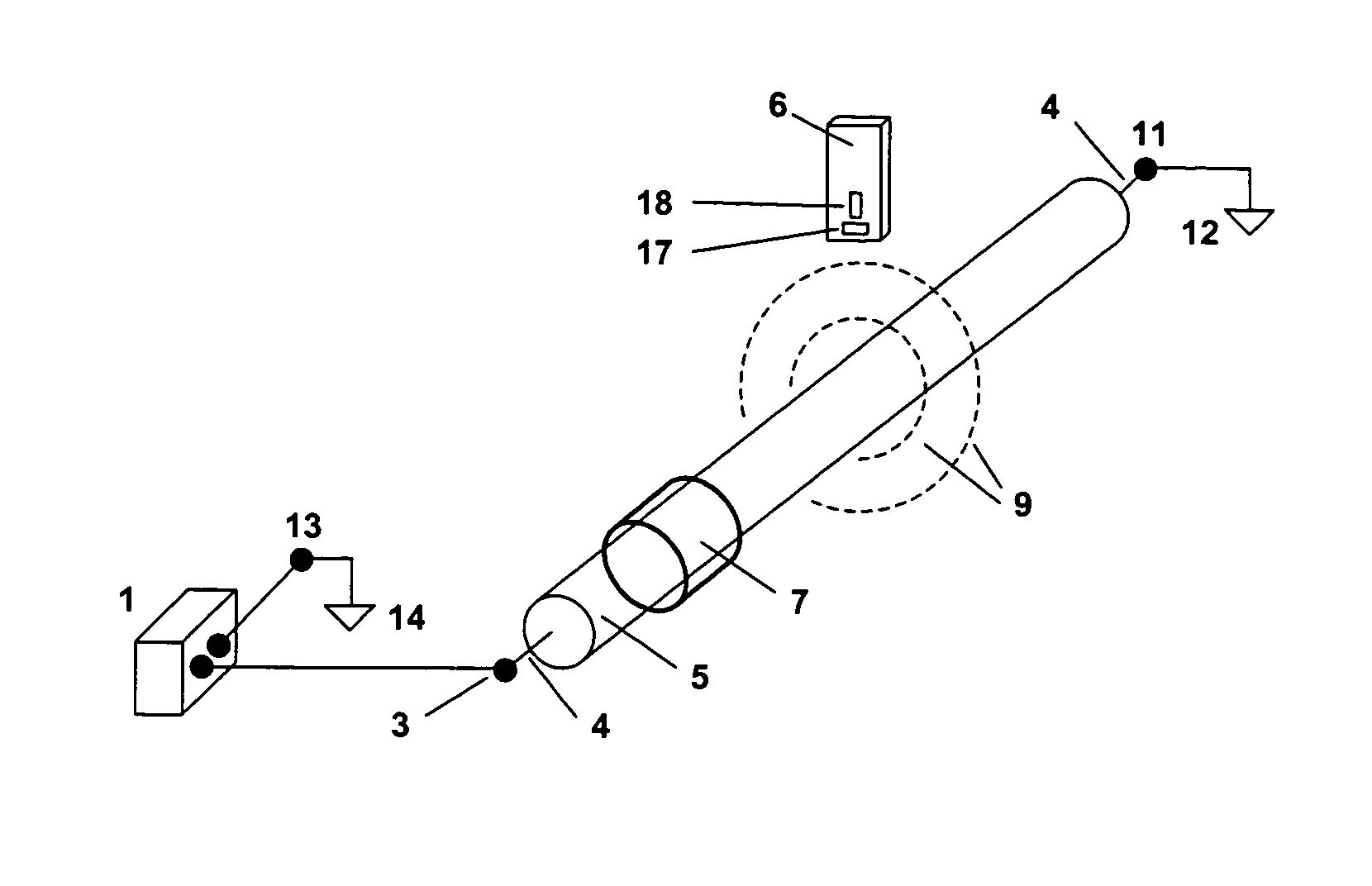
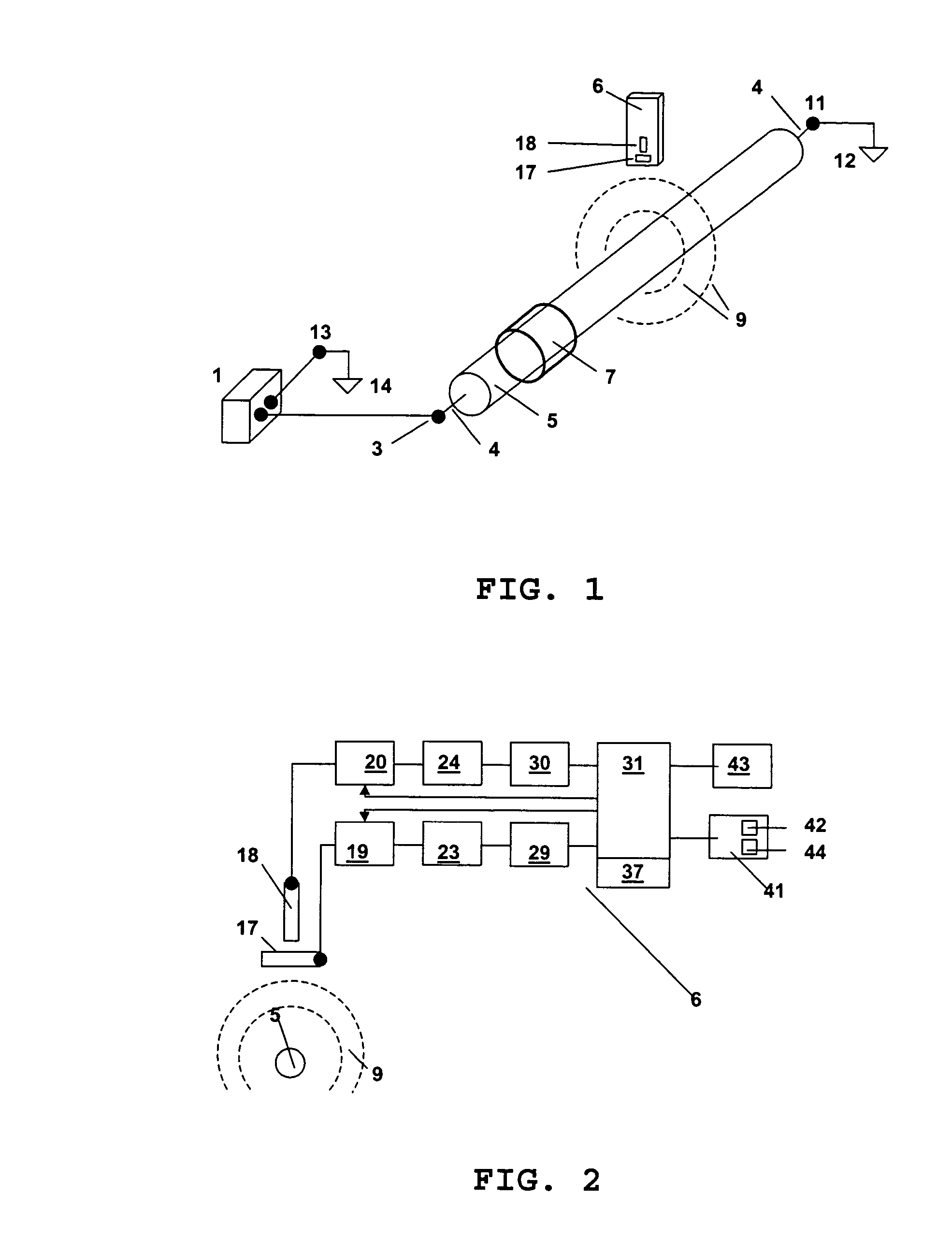
[0036] Systems and methods according to embodiments of the present invention concern location in a buried cable of cable splices and cable faults, for example connection splices, branch splices and sheath faults. In some embodiments, an audio frequency generator is coupled to the cable. The cable route can then be traced with an audio frequency tuned receiver according to the present invention. Test values related to the magnitude of orthogonal components of the magnetic field, for example the horizontal and vertical components, at various test points along the cable route can be recorded. A degree of inhomogeneity can be determined in the magnetic field and displayed in a line graph. Cable splices and faults are clearly identified by the degree of inhomogeneity in the magnetic field strength. In some embodiments of the invention, the test values can be read out of the receiver through an interface to allow for further processing of the data.

[0037]FIG. 1 shows a system for locating...


PUM


Abstract

A method and apparatus for the location and indication of cable splices and cable faults is disclosed. An audio frequency generator can be coupled to a cable under test and the magnetic field generated by the cable can be monitored by a receiver. A receiver includes at least two antenna coils situated to detect orthogonal components of the magnetic field. From test values measured at various test points along the cable route, a degree of inhomogeneity of the magnetic field along the cable route can be determined and displayed. Location of a cable fault and cable splice is then apparent in the display.

Description

RELATED APPLICATIONS [0001] This disclosure claims priority to German filed application DE 102 34 537.6, filed on Jul. 30, 2002, assigned to the same assignee as is the present disclosure, herein incorporated by reference in its entirety. BACKGROUND [0002] 1. Field of the Invention [0003] This invention relates to the location of faults in a buried cable and, more specifically, to a method and apparatus for the location of cable splices and cable faults. [0004] 2. Discussion of Related Art [0005] Various methods are utilized in practice to locate cable splices and cable faults. There are proven methods to locate cable splices, for example location with the twist method and the location with the minimum distortion method. [0006] For location according to the twist method, both poles of a generator operating at an audio frequency are connected to two inside conductors at the near end of a cable. This arrangement generates a field along the cable route, the so-called twist field, that,...

Claims


Application Information

Patent Timeline
IPC IPC(8): G01R31/02G01R31/08
CPCG01R31/083
Inventor FRAEDRICH, VOLKER
Owner HAGENUK KMT KABELMESSTECHN
Why Eureka
Try Eureka