Method of controlling laser oscillation of pulsed laser and pulsed laser system

Inactive Publication Date: 2006-08-17
RIKEN
View PDF6 Cites 29 Cited by
  • Summary
  • Abstract
  • Description
  • Claims
  • Application Information

AI Technical Summary

Benefits of technology

[0032] Consequently, according to the present invention, in optical machining technology, optical recording technology or the like which uses various kinds of pulsed lasers like ultra-short pulsed lasers such as a femtosecond laser and short pulsed lasers s

Problems solved by technology

However, engineering development regarding the positional control of the condensing spot of the ultra-short pulsed laser beam is not considered at all in the conventional methods, and there existed a problem of no method for detecting highly accurately where the condensing spot of the ultra-short laser beam is located on an object to be illuminated.
However, in all of

Method used


Image

  • Method of controlling laser oscillation of pulsed laser and pulsed laser system
  • Method of controlling laser oscillation of pulsed laser and pulsed laser system
  • Method of controlling laser oscillation of pulsed laser and pulsed laser system

Examples


first embodiment

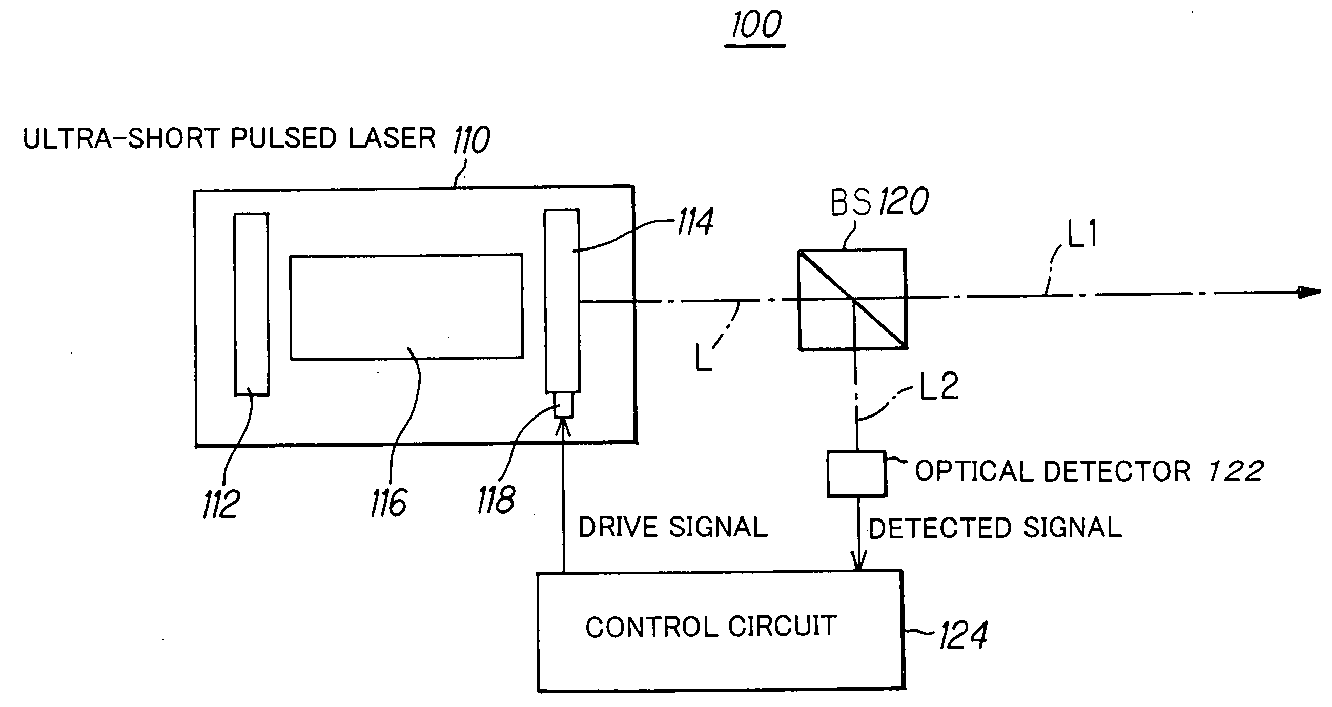
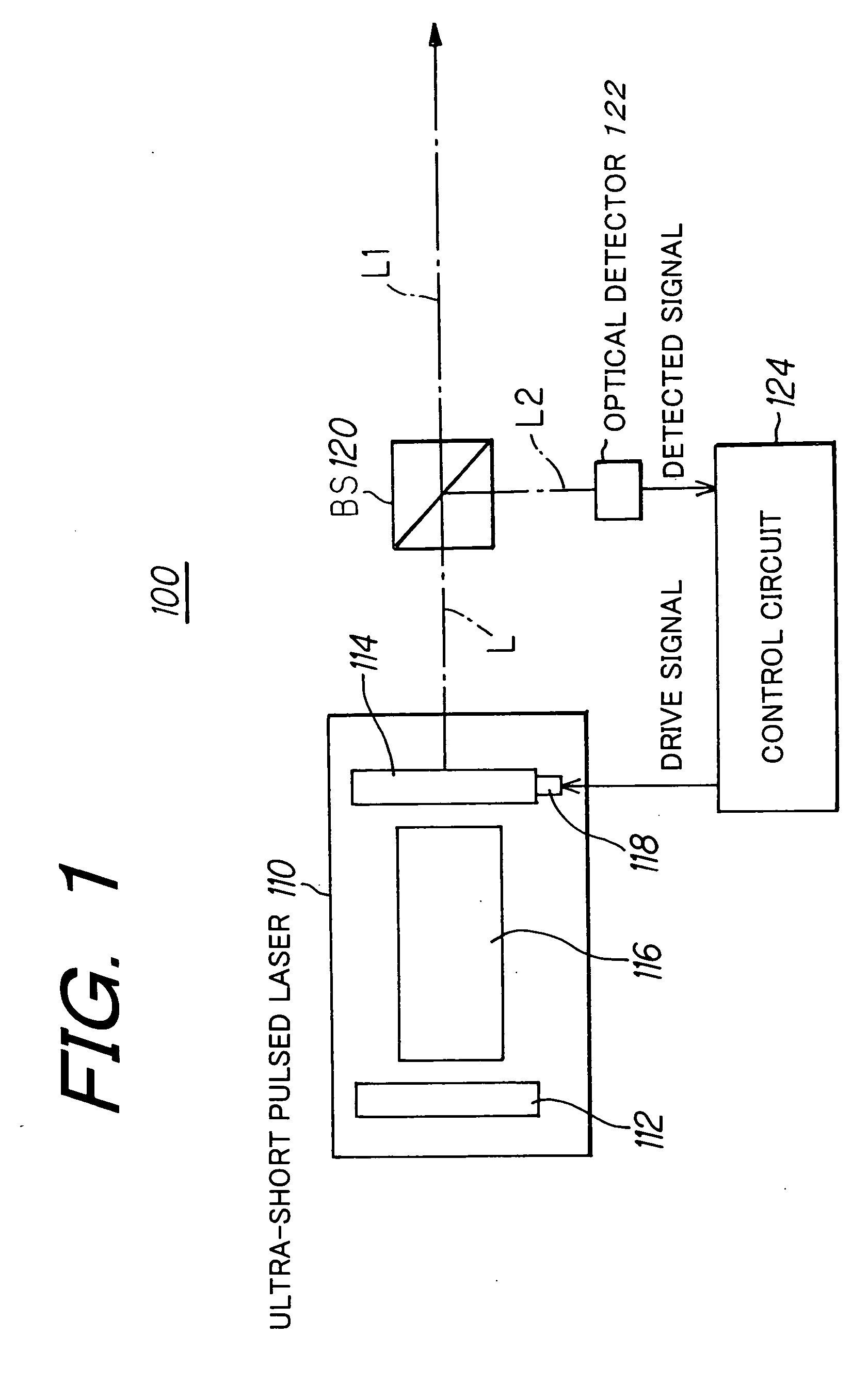
[0046]FIG. 1 is shows the conceptual constitution exemplary view of the pulsed laser system according to the present invention.

[0047] The pulsed laser system 100 includes an ultra-short pulsed laser 110 such as a femtosecond laser, for example, which has a laser resonator that is constituted by having a pair or mirrors of an end mirror 112 and an output mirror 114, and a laser medium 116 arranged between the end mirror 112 and the output mirror 114 of the laser resonator.

[0048] Further, the pulsed laser system 100 also includes an actuator 118 that consists of a piezoelectric element, for example, which changes the position of the output mirror 114 such as an arranged position or tilt along an optical axis.

[0049] Furthermore, the pulsed laser system 100 includes a beam splitter (BS) 120 that splits output beam L from the ultra-short pulsed laser 110 into beams (L1, L2) of two optical paths, an optical detector 122 that detects the ratio between pulse component of beam L2 of one op...

second embodiment

[0088] Next, FIG. 5 shows the conceptual constitution exemplary view of the pulsed laser system according to the present invention.

[0089] The pulsed laser system 200 is different from the pulsed laser system 100 on the point that it uses a deformable mirror or the like which is capable of changing the external shape such as the radius of curvature on a reflection surface, for example, is used as an end mirror 212, and the actuator 118 controlled by a drive signal output from the control circuit 124 is disposed on the end mirror 212 in order to change the external shape such as the radius of curvature on the reflection surface of the end mirror 212.

[0090] It is to be noted that the deformable mirror is a mirror where the piezoelectric element or an array of electrostatic actuators is arranged on a mirror rear surface and which can directly control the external shape of the mirror by appropriately controlling them.

[0091] In the above-described construction, in the pulsed laser syste...

third embodiment

[0101] Next, FIG. 7 shows the conceptual constitution exemplary view of the pulsed laser system according to the present invention.

[0102] The pulsed laser system 300 is different from the pulsed laser system 100 on the point that the ultra-short pulsed laser 110 includes an external resonator 302 as amplification means for amplifying the output beam from a laser resonator, which is constituted by having the pair of mirrors formed by the end mirror 112 and the output mirror 114, outside the laser resonator, and the actuator 118 controlled by drive signal output from the control circuit 124 is disposed on a mirror or a prism, which is a constituent member of the external resonator 302, in order to control the position or the external shape of the constituent member.

[0103] In the pulsed laser system 300, by controlling the external resonator 302 being the amplification means based on the drive signal output from the control circuit 124, that is, by controlling the position or the exte...


PUM

PropertyMeasurementUnit
Shapeaaaaaaaaaa
Environmental propertiesaaaaaaaaaa
Reflectionaaaaaaaaaa

Abstract

In order to perform positional control of a condensing spot of pulsed laser beam highly accurately when performing optical modeling, optical recording or the like in optical machining technology, optical recording technology or the like which uses various kinds of pulsed laser, which are ultra-short pulsed lasers such as a femtosecond laser and short pulsed laser such as a picosecond laser and a sub-picosecond laser, as a light source, a pulsed laser system detects an output beam from a pulsed laser, controls laser oscillation of the pulsed laser based on the detection result such the output beam contains CW laser beam together with pulsed laser beam, and allows the pulsed laser to output the pulsed laser beam and the CW laser beam simultaneously as the output beam from the pulsed laser.

Description

BACKGROUND OF THE INVENTION [0001] 1. Field of the Invention [0002] The present invention relates to a method of controlling laser oscillation of a pulsed laser and a pulsed laser system, more particularly to a method of controlling laser oscillation of a pulsed laser and a pulsed laser system which are preferably used in ultra-short pulsed lasers such as a femtosecond laser and short pulsed lasers such as a picosecond laser and a sub-picosecond laser. [0003] 2. Description of the Related Art [0004] In recent years, engineering development has been actively done where ultra-short pulsed lasers such as a femtosecond laser are used as a light source in optical recording technology such as an optical memory and optical machining technology such as optical modeling. [0005] For example, Japanese Patent Laid-open No. 2003-1599 publication discloses a method where femtosecond laser beam output from a femtosecond laser is condensed in photo-curable resin to manufacture a three-dimensional m...

Claims


Application Information

Patent Timeline
IPC IPC(8): H01S3/10
CPCB23K26/0635B23K26/426H01S3/082H01S3/106H01S3/1106H01S3/139B23K26/705B23K26/0624
Inventor TANAKA, TAKUOHAYASHI, TAKAYUKIKAWATA, SATOSHI
Owner RIKEN
Why Eureka
Try Eureka