Contact sensors and methods for making same

Inactive Publication Date: 2006-08-17
CLEMSON UNIV RES FOUND
View PDF36 Cites 77 Cited by
  • Summary
  • Abstract
  • Description
  • Claims
  • Application Information

AI Technical Summary

Benefits of technology

[0005] In one embodiment, the present invention is directed to a contact sensor. The sensor includes an electrically conductive composite material comprising a polymer and a conductive filler. Generally, the composite material can include any polymer. In certain embodiments, the polymer can be an engineering polymer or a high performance polymer. In one preferred embodiment, the composite material can include ultra-high molecular weight polyethylene (

Problems solved by technology

These film sensors, while generally suitable for examining static contact characteristics between two generally flat surfaces, have presented many difficulties in other situations.
For instance, when examining contact data between more complex surfaces, surfaces including complex curvatures, for instance, it can be difficult to conform the films to fit the surfaces without degrading the sensor's performance.
More serious problems exist with these materials as well.
For instance, film-based contact sensor devices and methods i

Method used


Image

  • Contact sensors and methods for making same
  • Contact sensors and methods for making same
  • Contact sensors and methods for making same

Examples


example 1

[0079] An industrial-grade UHMWPE powder (GUR 1150, available from Ticona Engineering Polymers) having a molecular weight of 6×10⁶, density of 0.93 g / mL, Tm of 135° C., and an average particle size of 100 μm, was combined with carbon black (CB) (Printex L-6 available from Degussa Hulls, Dusseldorf, Germany) having a primary particle size of 18 nm and dibutyl phthalate absorption of 120 mL / 100 g. Amounts of each powder were placed in a 120 mL plastic sample container and initially manually shaken for 5 minutes to obtain four different samples having CB weight percentages of 0.25%, 0.5%, 1%, and 8%. The samples were then mixed for 10 minutes on a common laboratory vortex at the maximum speed setting.

[0080] Virgin UHMWPE powder and the four UHMWPE / CB powder mixtures were then compression-molded into rectangular sheets 12 cm long, 8.5 cm wide, and 2 mm thick using a mold consisting of a 2 mm thick Teflon frame sandwiched between 2 stainless steel plates that were coated with Teflon mol...

example 2

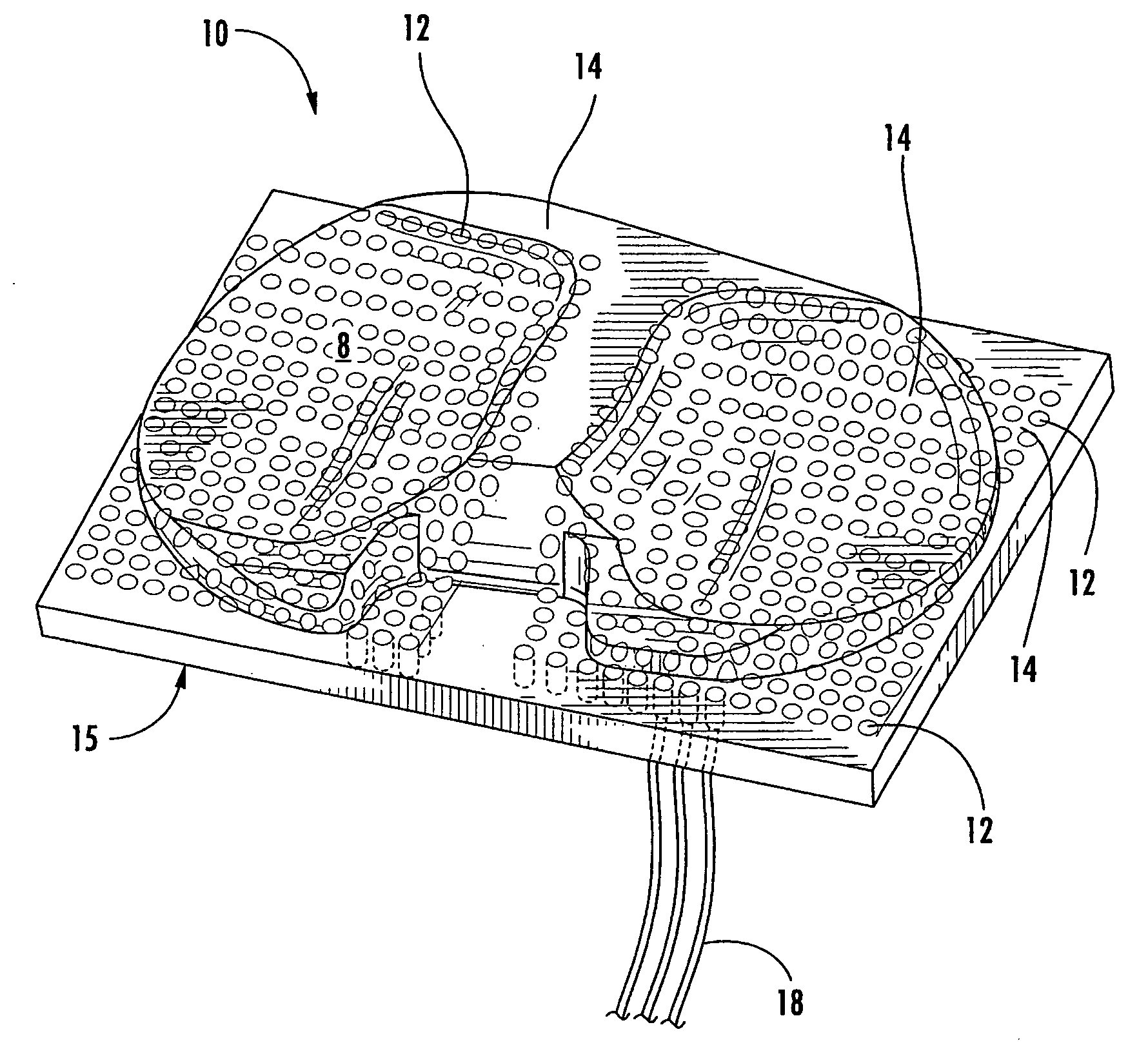
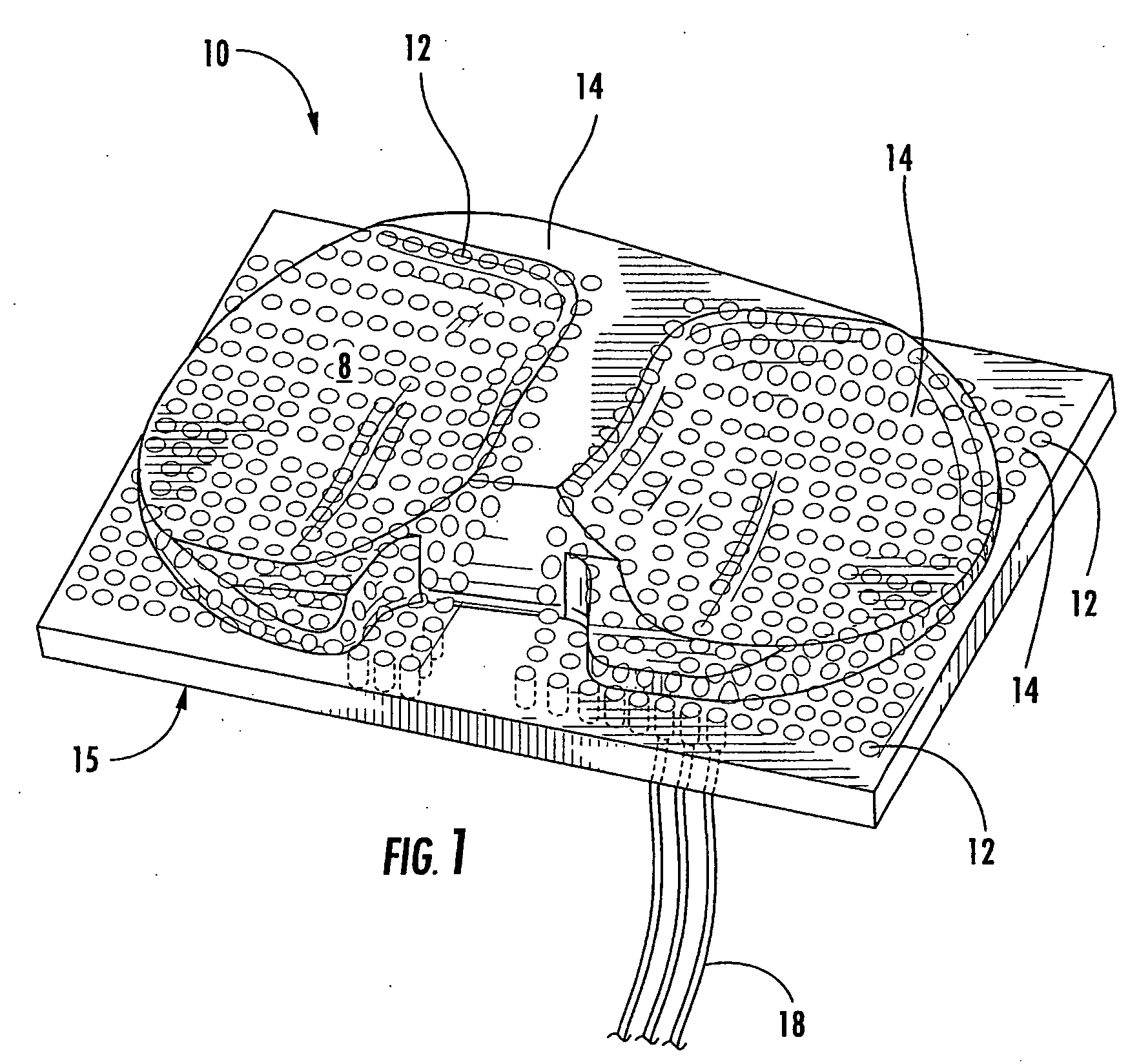
[0088] Compression molding was used to form 2 rectangular blocks of 1150 UHMWPE doped with 8 wt % carbon black filler as described above for Example 1. The blocks formed included a 28×18 matrix of surface sensing points 12 as shown in FIG. 1. The points were circular with a 1 / 16th inch (1.59 mm) diameter and spaced every 1 / 10th inch (2.54 mm). The blocks were then machined to form both a highly-conforming, PCL-sacrificing tibial insert (Natural Knee II, Ultra-congruent size 3, Centerpulse Orthopedics, Austin, Tex.) and a less conforming PCL-retaining tibial insert (Natural Knee II, Standard-congruent, size 3, Centerpulse Orthopedics, Austin, Tex.) as illustrated in FIG. 1. The implants were then aligned and potted directly in PMMA in the tibial fixture of a multi-axis, force-controlled knee joint simulator (Stanmore / Instron, Model KC Knee Simulator). Static testing was performed with an axial load of 2.9 kN (4×B.W.) at flexion angles of 0°, 30°, 60°, and 80°, to eliminate the effect...

example 3

[0091] Tecoflex SG-80A, a medical grade soft polyurethane available from Thermedics Inc. (Woburn, Mass.), was solution processed and molded including 4 wt % and 48 wt % CB to form two solid sample materials. FIGS. 13A and 13B graphically illustrate the resistance vs. compressive force applied to the samples for the 4% and 48% non-surfactant mixed samples, respectively. As can be seen, both samples showed pressure sensitive conductive characteristics suitable for forming the sensors of the present invention where the value of resistance can be controlled with the amount of conductive filler added.


PUM


Abstract

The present invention is directed to novel contact sensors. The contact sensors of the invention include a conductive composite material formed of a polymer and a conductive filler. In one particular embodiment, the composite materials can include less than about 10 wt % conductive filler. Thus, the composite material of the contact sensors can have physical characteristics essentially identical to the polymer, while being electrically conductive with the electrical resistance proportional to the load on the sensor. If desired, the sensors can be formed of the same polymeric material as the bearing that is being examined. The sensors can provide real time dynamic contact information for joint members under conditions expected during use. In one particular embodiment, the sensors can be used to examine dynamic wear characteristics of artificial joint bearings such as artificial knee, hip, or shoulder bearings.

Description

BACKGROUND OF THE INVENTION [0001] Contact sensors have been used to gather information concerning contact or near-contact between two surfaces in medical applications, such as dentistry, podiatry, and in the development of prostheses, as well as in industrial applications, for instance to determine load and uniformity of pressure between mating surfaces, and in the development of bearings and gaskets. In general, these sensors include pressure-sensitive films designed to be placed between mating surfaces. These film sensors, while generally suitable for examining static contact characteristics between two generally flat surfaces, have presented many difficulties in other situations. For instance, when examining contact data between more complex surfaces, surfaces including complex curvatures, for instance, it can be difficult to conform the films to fit the surfaces without degrading the sensor's performance. [0002] More serious problems exist with these materials as well. For inst...

Claims


Application Information

Patent Timeline
IPC IPC(8): A61B5/103
CPCA61B5/107A61B5/4528A61B2019/464G01L1/205A61B2562/0247A61B2090/064
Inventor CLARK, ANDREW C.LABERGE, MARTINE
Owner CLEMSON UNIV RES FOUND
Why Eureka
Try Eureka