Thermal management system for a vehicle

Active Publication Date: 2006-08-24
EMP ADVANCED DEVMENT
View PDF47 Cites 38 Cited by
  • Summary
  • Abstract
  • Description
  • Claims
  • Application Information

AI Technical Summary

Benefits of technology

[0010] The invention also provides a thermal management system for a vehicle including an engine. An exhaust cooler is configured to receive exhaust gas from the engine and to cool the exhaust gas as it passes through it. A first valve is operable to control the amount of exhaust gas passing through the exhaust gas cooler. An air intake system receives intake air for the engine. The intake system includes a compressor operable to compress the intake air. The intake system is configured to deliver the compressed intake air downstream from the first valve, thereby forming a mixed gas including the compressed intake air and the exhaust gas. A mixed gas cooler is located downstream from the first valve for cooling the mixed gas as it passes through the mixed gas cooler. A first heat exchanger is in fluid communication with the mixed gas cooler for transferring heat from the coolant to the ambient air. A pump is operable to pump a coolant through the mixed gas cooler and the exhaust gas cooler, thereby facilitating respective heat transfer from the mixed gas and

Problems solved by technology

Although EGR systems used on vehicles today may be helpful to reduce the temperature of combustion in the engine cylinders, they may not provide a high degree o

Method used


Image

  • Thermal management system for a vehicle
  • Thermal management system for a vehicle
  • Thermal management system for a vehicle

Examples


Embodiment Construction

)

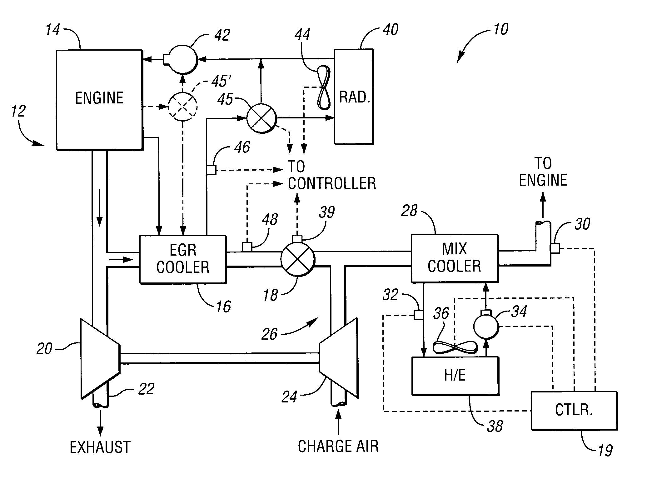
[0024]FIG. 1 shows a vehicle thermal management system 10 in accordance with the present invention. Also shown in FIG. 1 is a portion of a vehicle 12, including an engine 14. The thermal management system 10 includes an exhaust gas cooler, or EGR cooler 16. As explained more fully below, the EGR cooler 16 cools the exhaust gas before it is recirculated back into the engine 14. An EGR valve 18 is located downstream from the EGR cooler 16, and is operable to control the amount of exhaust gas passing through the EGR cooler 16. By placing the EGR valve 18 downstream from the EGR cooler 16, the exhaust gas is cooled when it reaches the EGR valve 18. This helps to avoid some of the deleterious effects that hot exhaust gas can have on a valve, thus helping to extend the life of the EGR valve 18.

[0025] Having the exhaust gas cooled prior to entering the EGR valve 18 also allows the use of a smaller valve. This is because the mass of the exhaust gas is greater after it has been cooled; wit...


PUM


Abstract

A vehicle thermal management system includes an exhaust gas cooler configured to receive exhaust gas from the engine and to cool the exhaust gas before it is recirculated back into the engine. A valve is located downstream from the exhaust gas cooler, and is operable to control the amount of exhaust gas passing through the exhaust gas cooler. Intake air mixes with the exhaust gas downstream from the first valve. The mixed gas is then cooled by a mixed gas cooler before it enters the engine intake manifold. A coolant is circulated through the mixed gas cooler and a heat exchanger. The mixed gas rejects heat to the coolant via the mixed gas cooler, and the coolant rejects heat to the ambient air via the heat exchanger.

Description

BACKGROUND OF THE INVENTION [0001] 1. Field of the Invention [0002] The present invention relates to a thermal management system for a vehicle. [0003] 2. Background Art [0004] In response to demands for improved fuel economy and reduced emissions, vehicles today are being manufactured with systems designed to increase combustion efficiency and reduce exhaust emissions. One way to reduce exhaust emissions, particularly in diesel engines, is to introduce some of the engine exhaust gas back into the combustion cylinders to lower the temperature of combustion. These systems, known as exhaust gas recirculation (EGR) systems can be particularly useful in reducing emissions of nitrogen-oxygen compounds, known collectively as NOx. [0005] A number of EGR systems are described in a Society of Automotive Engineers (SAE) Technical Paper, Document Number 2001-01-1732, entitled “Thermal Management Evolution and Controlled Coolant Flow,” copyright 2001. One such system includes a controllable elec...

Claims


Application Information

Patent Timeline
IPC IPC(8): F02B29/04
CPCF02B29/0493F02M25/0707F02M25/0727F02M25/0738F02M25/0754Y02T10/121Y02T10/146F02M26/05F02M26/23F02M26/33F02M26/47Y02T10/12
Inventor CHALGREN, ROBERT D.LASECKI, MICHAEL P.MARTIN, MICHAEL W.HOLLIS, THOMAS J.BADER, MARK S.ALLEN, DAVID J.
Owner EMP ADVANCED DEVMENT
Why Eureka
Try Eureka