Effusion Cell Valve

a technology of effusion cell valve and valve body, which is applied in vacuum evaporation coating, crystal growth process, coating, etc., can solve the problems of thin film contamination and limit the geometry that is attainable with pbn

Inactive Publication Date: 2006-08-24
ESCI
View PDF15 Cites 19 Cited by
  • Summary
  • Abstract
  • Description
  • Claims
  • Application Information

AI Technical Summary

Benefits of technology

[0011] These and other aspects of the present invention will be more apparent from the following description.

Problems solved by technology

If there is a reaction between the source material and the containing vessel or valve components the thin films become contaminated.
There are limitations on the geometry that is attainable with PBN because of the restrictive fabrication process that is required to produce the components.

Method used


Image

  • Effusion Cell Valve
  • Effusion Cell Valve
  • Effusion Cell Valve

Examples


Embodiment Construction

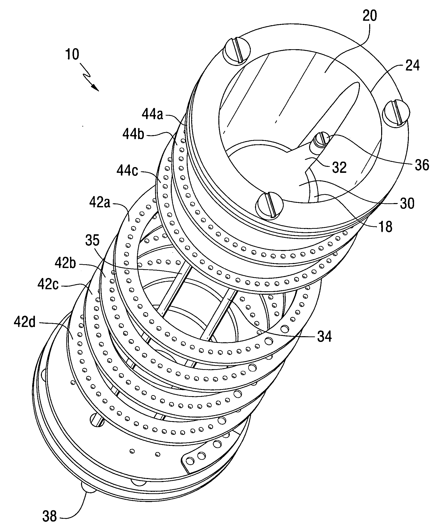
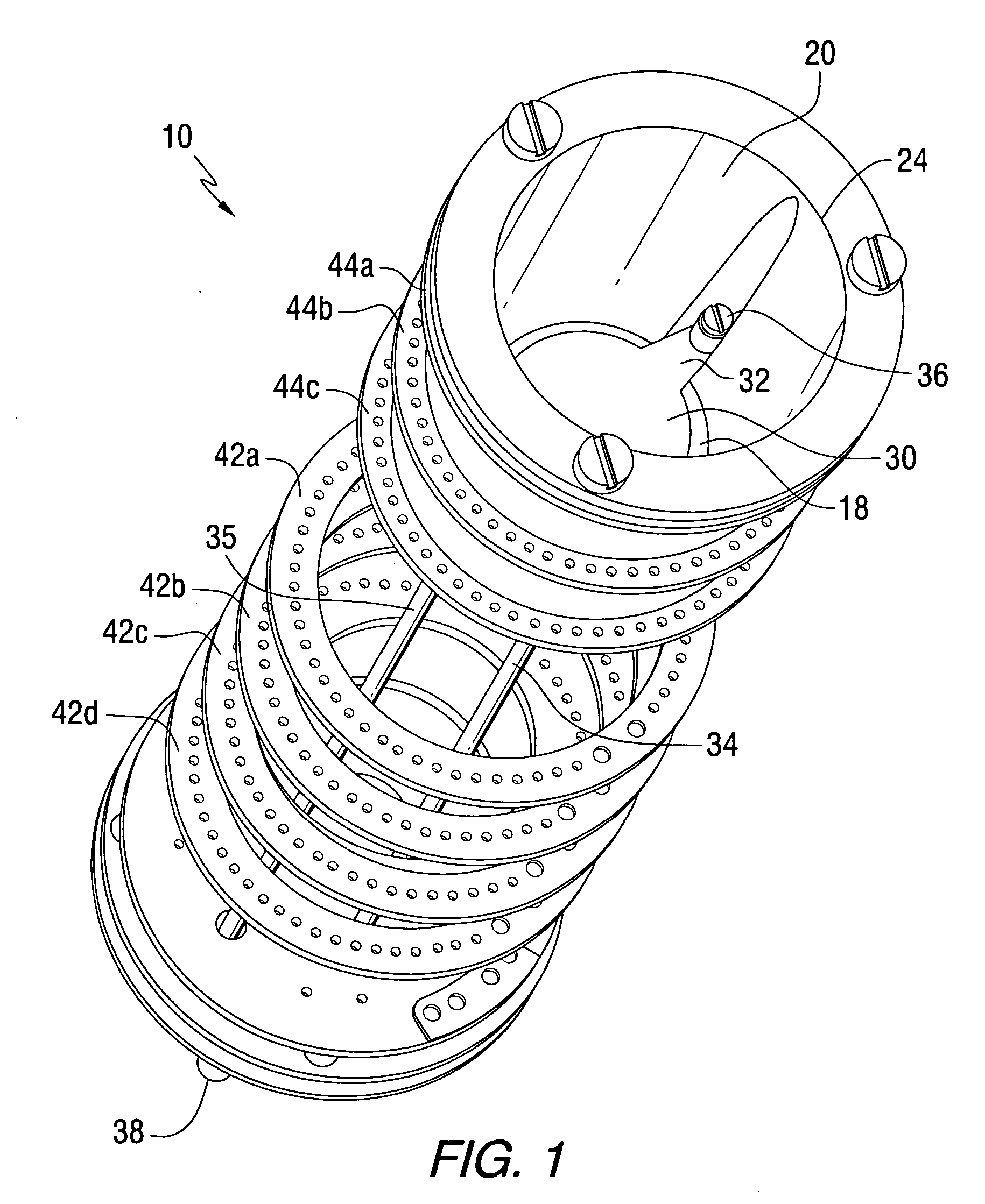
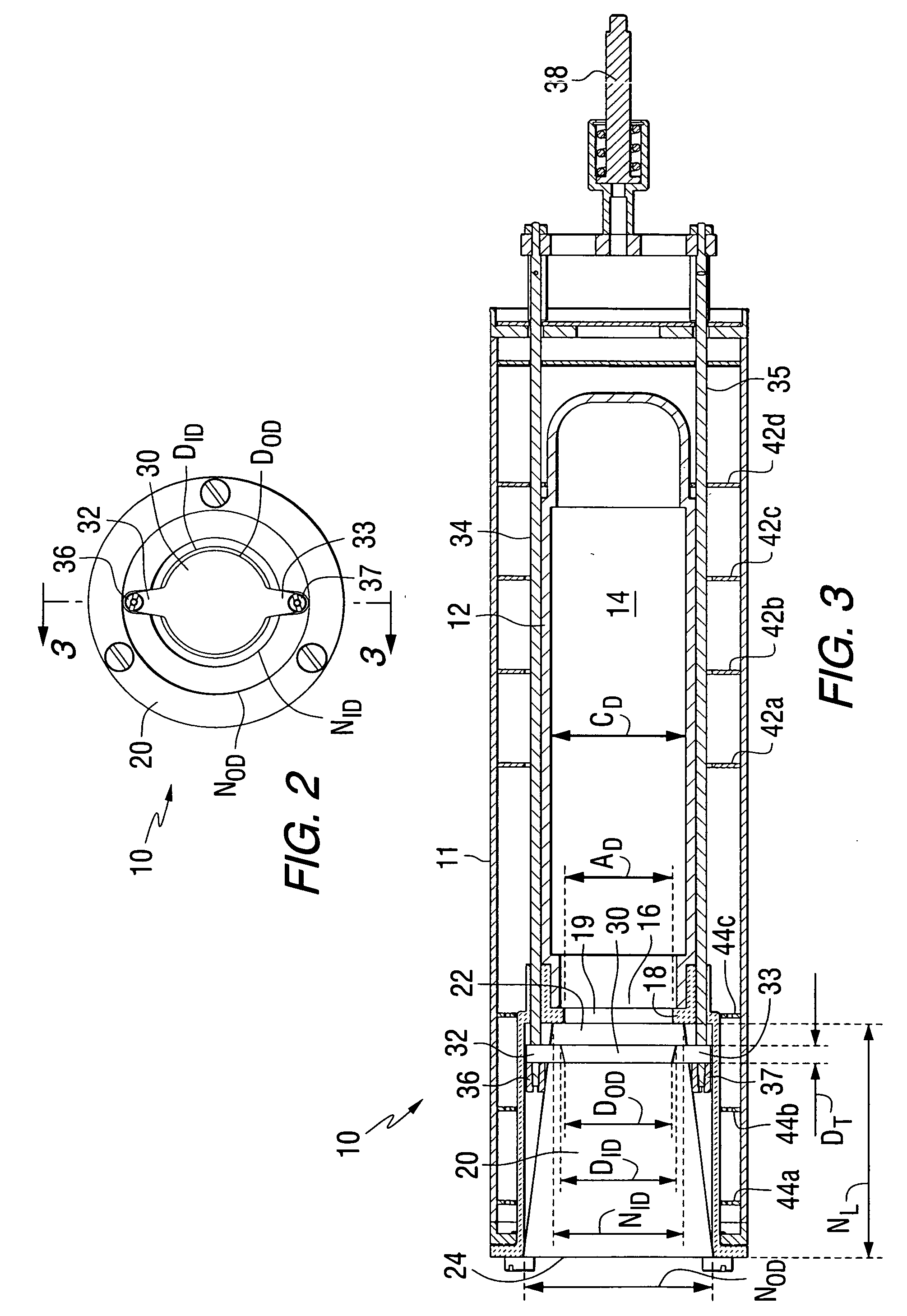
[0021]FIGS. 1-4 illustrate an effusion cell 10 in accordance with an embodiment of the present invention. In FIGS. 1 and 2, the effusion cell 10 is shown without its outer enclosure, while in FIGS. 3 and 4 the cylindrical enclosure 11 is shown. The enclosure may be made of any suitable material such as tantalum, e.g., inner and outer tantalum sleeves separated by an insulating layer of knurled tantalum foil. The effusion cell 10 includes a crucible 12, shown in FIGS. 3 and 4, made of a material such as graphite, silicon carbide or the like. The crucible 12 has a crucible chamber 14 with an open end 16. A valve seat 18 having an opening or aperture 19 is mounted at the open end 16 of the crucible 12 by means such as a press fitting, a threaded connection or fasteners. The crucible 12 has an inner diameter CD, while the valve seat aperture 19 has a diameter AD. In one embodiment, the ratio of AD:CD may be relatively large, e.g., greater than 0.2:1, typically greater than 0.5:1. Howeve...


PUM

PropertyMeasurementUnit
taper angleaaaaaaaaaa
angleaaaaaaaaaa
taper angleaaaaaaaaaa

Abstract

A valve for an effusion cell is disclosed. The valve includes a valve seat having an opening in communication with an interior chamber of a heating crucible. A disk-shaped valve member is axially movable with respect to the valve seat in order to increase or decrease the effective size of the valve seat opening. An outlet nozzle may be provided downstream from the valve seat. The valve provides mechanical adjustment of the deposition rate of the evaporated material replacing thermal changes as the means to control the deposition rate or flux from the effusion cell. The nozzle, valve disk and valve seat may be made of machined graphite coated with a carbon-containing material such as pyrolytic graphite, silicon carbide, or the like. The effusion cell may be used for molecular beam epitaxial growth of various materials incorporating mechanical control of the flux without negatively impacting the state of the art qualities of the deposited films with respect to deposition uniformity, surface morphology and background doping.

Description

CROSS REFERENCE TO RELATED APPLICATION [0001] This application claims the benefit of U.S. Provisional Patent Application Ser. No. 60 / 655,124 filed Feb. 22, 2005, which is incorporated herein by reference.FIELD OF THE INVENTION [0002] The invention relates to vacuum evaporation, and more particularly relates to valves used in effusion-type evaporative cells. BACKGROUND INFORMATION [0003] Vacuum deposition techniques are used to deposited different types of materials onto substrates to form thin films. Vapor sources that modulate the flux with an integral metal needle valve or a movable metal shutter are known in the art of molecular beam epitaxy (MBE). The majority of solid or molten source materials and the resulting vapors are reactive with metals at elevated temperatures. Thus, the current MBE sources with metal valves or metal shutters may only be used with a few relatively non-reactive source materials. If there is a reaction between the source material and the containing vessel...

Claims


Application Information

Patent Timeline
Patent Type & Authority Applications(United States)
IPC IPC(8): C23C16/00
CPCC23C14/243C30B23/066
Inventor BICHRT, CRAIG E.
Owner ESCI
Why Eureka
Try Eureka