Method for controlling an inlet valve of an internal combustion engine

a technology of internal combustion engine and inlet valve, which is applied in the direction of machines/engines, non-mechanical valves, output power, etc., can solve the problems of high gas inflow speed, achieve the effect of saving installation space, simple design, and saving installation spa

Inactive Publication Date: 2006-08-24
DAIMLER AG
View PDF8 Cites 6 Cited by
  • Summary
  • Abstract
  • Description
  • Claims
  • Application Information

AI Technical Summary

Benefits of technology

[0011] A particularly simple, cost-effective design which also saves installation space is obtained by keeping the closing time of the second inlet valve constant over the entire rotational speed range. The second inlet valve does not need to be controllable here and can be actuated, for example, by means of a fixed cam.
[0012] The closing time of the first inlet valve advantageously lies before the closing time of the second inlet valve below a third engine speed which lies between the first and second engine speeds. As a result, a good amount of swirl can be generated in the entire rotational speed range below the third engine speed. Here, the third engine speed expediently lies above the rotational speed range in which a high degree of swirl has a positive effect on the power and the em

Problems solved by technology

As a result, a partial vacuum can be produced in the cylinder,

Method used


Image

  • Method for controlling an inlet valve of an internal combustion engine
  • Method for controlling an inlet valve of an internal combustion engine
  • Method for controlling an inlet valve of an internal combustion engine

Examples


Embodiment Construction

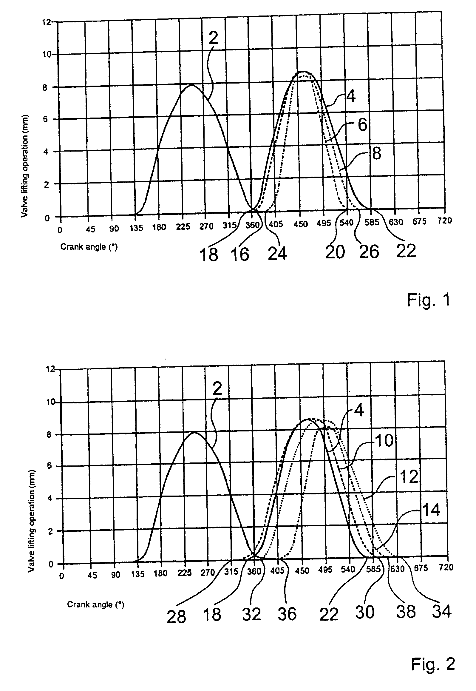
[0022]FIG. 1 and FIG. 2 each show the valve lift operation of two inlet valves and one outlet valve of a cylinder in a diagram in which the valve lift operation is plotted over the crank angle. In this context it is irrelevant for the explanation of the exemplary embodiments whether the cylinder has additional valves. The valve lift curve 2 for the outlet valve is illustrated left of the top dead center position, marked by 360°, and possible valve lift curves 4, 6, 8, 10, 12, 14 of the inlet valves are illustrated to the right of the top dead center location.

[0023]FIG. 1 shows possible valve lift control procedures for the inlet valves at a first engine speed, which typically lies in the lower rotational speed range of the internal combustion engine. The first of the two inlet valves is equipped with a variable valve control system, while the second inlet valve is actuated in rigid fashion, for example by a simple cam. The second inlet valve has a valve lift actuation 4 which is th...


PUM


Abstract

In a method for controlling an inlet valve of an internal combustion engine having at least one cylinder with at least a first inlet valve and a second inlet valve, wherein the closing time of the first inlet valve is adjustable and the first inlet valve is so controlled that, at a first engine speed, the first inlet valve is closed before the closing of the second inlet valve and, at a second engine speed which is higher than the first engine speed, the first inlet valve is closed after the closing time of the second inlet valve.

Description

[0001] This is a Continuation-In-Part Application of International Application PCT / EP2004 / 000501 filed 01 / 22 / 04 and claiming the priority of German application 103 07 167.9 filed 02 / 20 / 03. BACKGROUND OF THE INVENTION [0002] The invention relates to a method of controlling an internal combustion engine with a cylinder having at least two inlet valves, the timing of at least one of which is adjustable. [0003] Internal combustion engines are designed to be operated over a wide rotational speed range. In order to obtain a high torque accompanied at the same time by an acceptable degree of efficiency and low exhaust gas emission values over the wide rotational speed range it is necessary to make compromises in the design of the valve geometry and the valve control system, the gas inlet system and the fuel supply. Internal combustion engines are usually operated more often in the lower rotational speed range than in the higher rotational speed range. For this reason it is particularly app...

Claims


Application Information

Patent Timeline
IPC IPC(8): F02B15/00F01L1/34F01L9/04F01L1/26F01L9/20F02D13/02
CPCF01L1/267F01L1/34F01L2820/01F02D13/0226F02D13/0234F02D13/0253F02D13/0257F02D13/0265F02D2013/0292Y02T10/12F01L9/20
Inventor HEEL, BERNHARDJUTZ, BERNHARDMARX, OLIVERPFAFF, RUDIGERSCHMIDT, TIMO
Owner DAIMLER AG
Why Eureka
Try Eureka