Extreme ultra violet light source device

a light source device and ultra-violet technology, applied in the field of light source devices, can solve the problems of reducing the reflectance, damage to the collection mirror, and reducing the life of the collection mirror, so as to reduce the running cost of the euv light source device, the collection mirror can be extended, and the effect of efficient collection

Active Publication Date: 2006-08-24
GIGAPHOTON
View PDF3 Cites 81 Cited by
  • Summary
  • Abstract
  • Description
  • Claims
  • Application Information

AI Technical Summary

Benefits of technology

[0009] The present invention has been achieved in view of the above-mentioned problems. An object of the present invention is to provide an extreme ultra violet light source device capable of extending the life of a collection mirror and reducing running cost by protecting the collection mirror from debris that is considered harmful to a mirror coating.
[0011] According to the present invention, the neutral particles included in debris is ionized by the ionizer, and therefore, not only the charged particles included in the debris but also the neutral particles can be trapped by the magnetic field formed within the chamber. Accordingly, the debris can be efficiently collected and the collection mirror can be protected from the debris that is considered harmful to a mirror coating. As a result, the life of the collection mirror can be extended and the running cost of the EUV light source device can be reduced.

Problems solved by technology

The melted solid material becomes debris having a diameter of several micrometers or more, which is emitted in large quantity and causes damage to the collection mirror (specifically, to the mirror coating) and reduces the reflectance thereof.
Also, in the case where a liquid material is used as the target, the flying debris causes damage to the collection mirror.
On the other hand, in the case where a gas is used as the target, although debris is reduced, the conversion efficiency from the power supplied to the driving laser to the power of the EUV light is reduced.

Method used


Image

  • Extreme ultra violet light source device
  • Extreme ultra violet light source device
  • Extreme ultra violet light source device

Examples


first embodiment

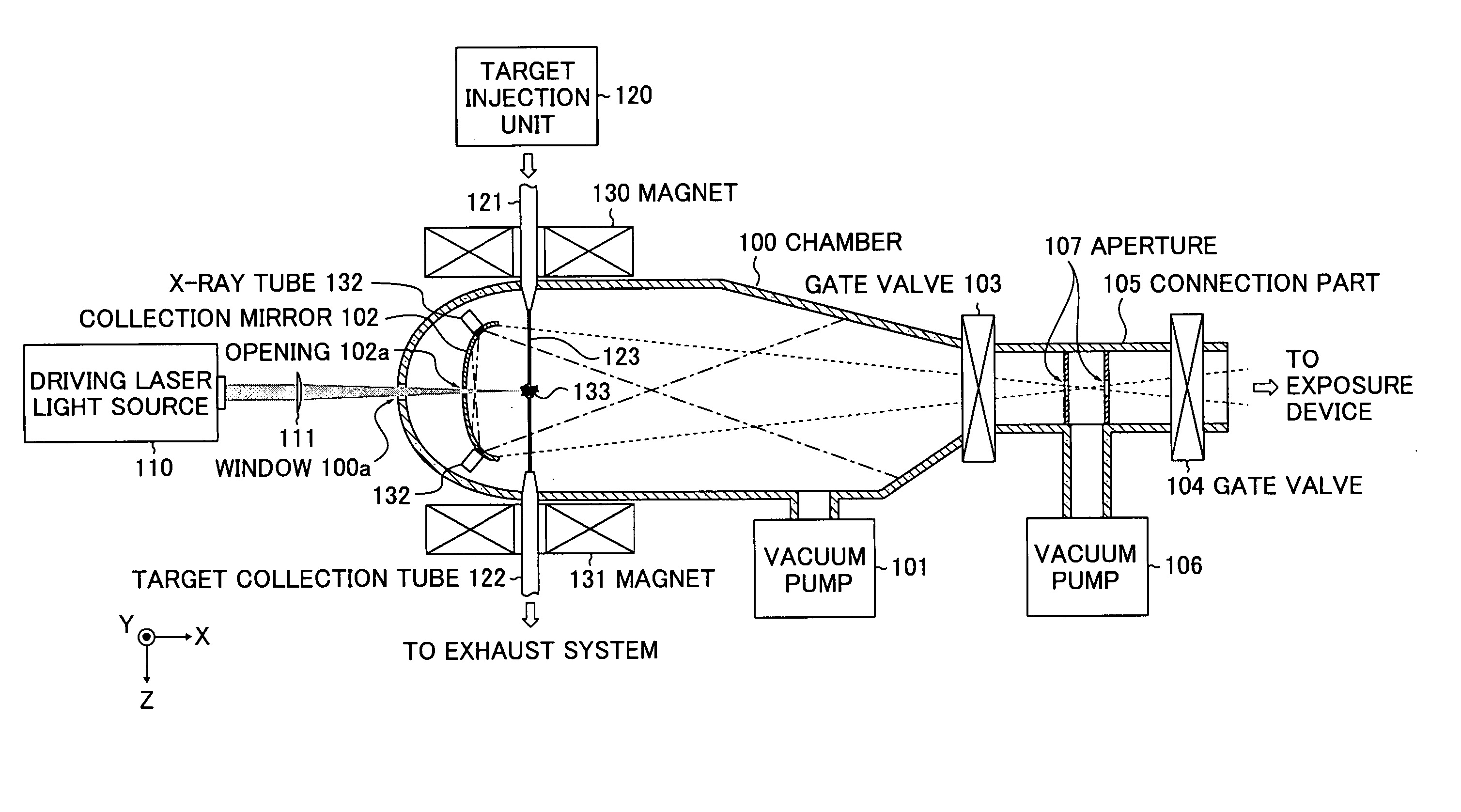
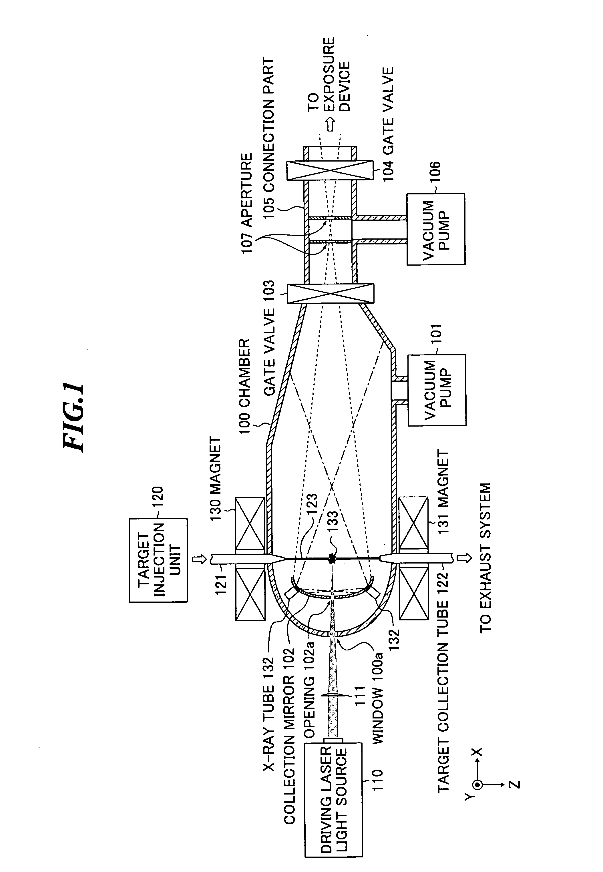
[0035] First, a basic configuration of an EUV (extreme ultra violet) light source device will be described by referring to FIG. 1. FIG. 1 is a schematic diagram showing a configuration of an extreme ultra violet light source device according to the present invention.

[0036] The EUV light source device shown in FIG. 1 includes a chamber 100, a driving laser light source 110 for generating a laser beam, an irradiation optical system 111 and a target injection unit 120. Further, in or near the chamber 100, a vacuum pump 101, a collection mirror 102, a target injection nozzle 121 and a target collection tube 122 are provided.

[0037] The air within the chamber 100 is exhausted by the vacuum pump 101, and thereby, maintained at predetermined pressure.

[0038] The driving laser light source 110 generates a laser beam for providing energy to a target material for excitation. Further, the irradiation optical system 111 collects the laser beam generated from the driving laser light source 110 a...

second embodiment

[0053]FIG. 4 is a schematic diagram showing a configuration of an EUV light source device according to the present invention. In the embodiment, the X-ray tubes 132 are provided between the EUV light generation plasma 133 and the collection mirror 102. Further, in the embodiment, the application directions of the respective X-ray tubes 132 are determined such that the EUV light generation plasma 133 comes to the end of the range of X-ray application in order to apply X-ray intensively to the space between EUV light generation plasma 133 and the collection mirror 102. Other configuration is the same as that of the EUV light source device shown in FIG. 1.

third embodiment

[0054]FIG. 5 is a schematic diagram showing a configuration of an EUV light source device according to the present invention.

[0055] In the above-mentioned first and second embodiments, the optical path of the laser beam, the orbit of the target material and the arrangement of the X-ray tubes 132 have been illustrated in the same plane, however, they are not necessarily in the same plane. For example, as shown in FIG. 5, the target material 123 may be injected toward Y-direction (the direction from the backside to the front side of the paper). Further, in the embodiment, the application directions of the respective X-ray tubes are determined such that the central axes of the output X-rays lies the collection mirror in order to apply X-ray intensively to the space between EUV light generation plasma 133 and the collection mirror 102.

[0056] Next, variations in arrangement of the plural X-ray tubes and magnets in the first to third embodiments of the present invention will be described...


PUM


Abstract

An EUV light source device for protecting a collection mirror from debris that is considered harmful to a mirror coating. The EUV light source device includes: a chamber in which extreme ultra violet light is generated; a target injection unit and a target injection nozzle that supply the chamber with a material to become the target; a laser light source that applies a laser beam to the target so as to generate plasma; a collection mirror that collects the extreme ultra violet light emitted from the plasma; an X-ray source that ionizes neutral particles included in particles emitted from the plasma into charged particles; and plural magnets that generate a magnetic field within the chamber so as to trap at least the charged particles ionized by the X-ray source.

Description

BACKGROUND OF THE INVENTION [0001] 1. Field of the Invention [0002] The present invention relates to a light source device for generating extreme ultra violet (EUV) light by applying a laser beam to a target. [0003] 2. Description of a Related Art [0004] As semiconductor processes become finer, the photolithography has been making rapid progress to finer fabrication, and, in the next generation, microfabrication of a pattern having a width of 100 nm to 70 nm, further, microfabrication of a pattern having a width of 50 nm or less will be required. For example, in order to fulfill the requirement for microfabrication of a pattern having a width of 50 nm or less, the development of exposure equipment with a combination of an EUV light source for generating light having a wavelength of about 13 nm and a reduced projection cataoptric system is expected. [0005] As the EUV light source, there are three kinds of an LPP (laser produced plasma) light source using plasma generated by applying ...

Claims


Application Information

Patent Timeline
Patent Type & Authority Applications(United States)
IPC IPC(8): G01J3/10
CPCB82Y10/00G03F7/70033G03F7/70916H05G2/003H05G2/008
Inventor IMAI, YOUSUKEHOSHINO, HIDEOKOMORI, HIROSHI
Owner GIGAPHOTON
Why Eureka
Try Eureka