
Sensorless control of two-phase brushless DC motor

Active Publication Date: 2006-08-24
ATMEL CORP
View PDF26 Cites 64 Cited by
  • Summary
  • Abstract
  • Description
  • Claims
  • Application Information

AI Technical Summary

Benefits of technology

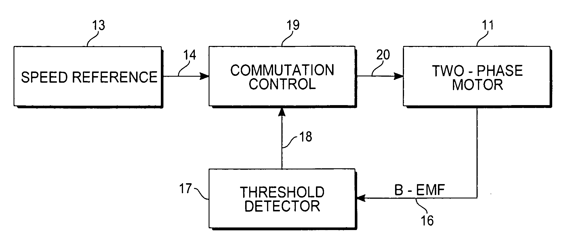
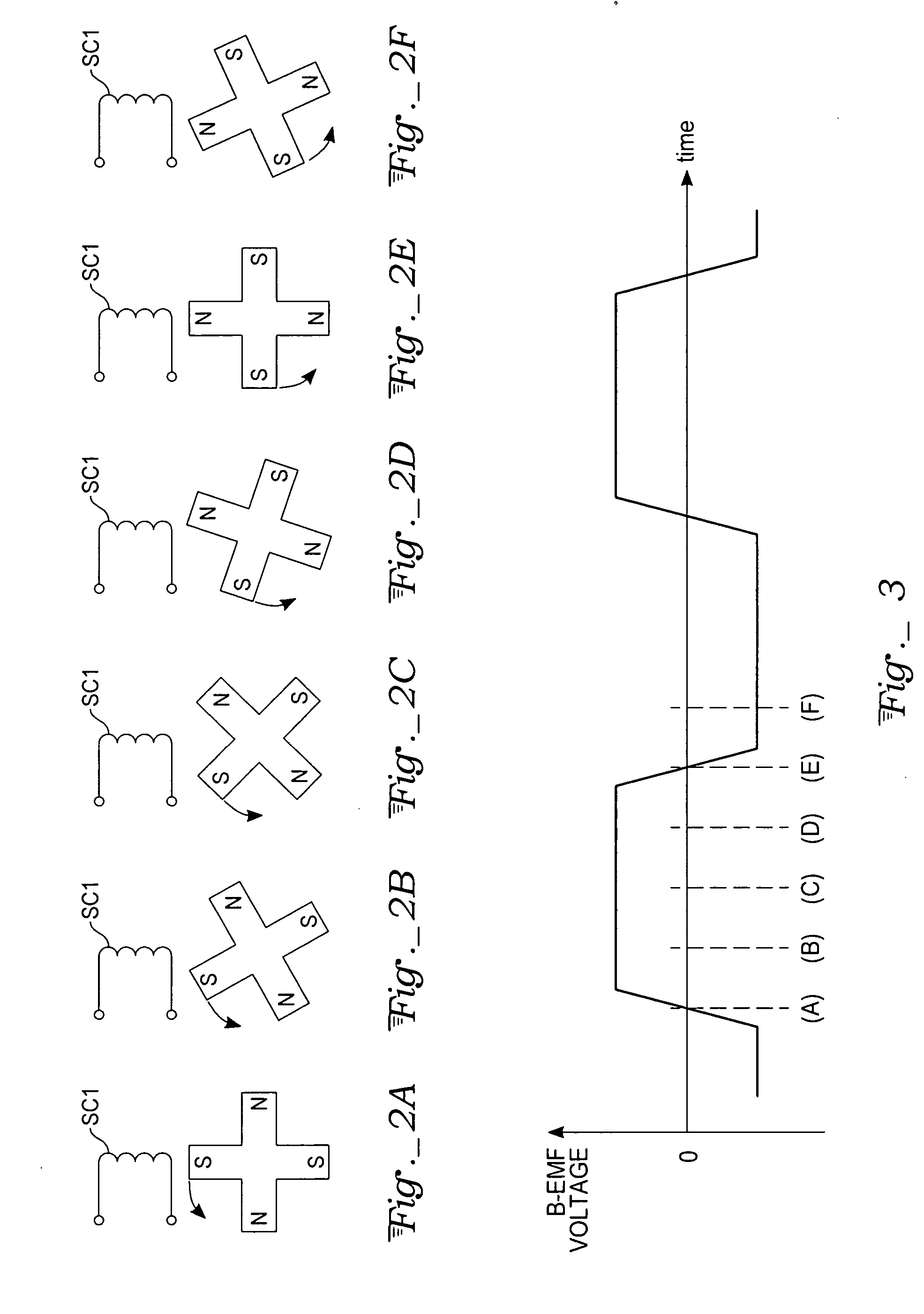
[0010] A control system is provided for a two-phase BLDC motor. The B-EMF signal over the two-phase motor's passive coil is used to determine when to perform the commutation of the current flow in the stator coils. An external speed reference is also supplied to the commutation control. Block (square-wave) commutation is used, together with an advance commutation technique to optimize the speed performance of the motor. The motor speed is controlled by a pulse width modulated (PWM) signal onto the commutation square-wave signal. A microcontroller is used to measure the EMF and control the commutation of the motor, and to measure an external speed reference that defines the desired speed of the motor.
[0011] In particular, a motor control system in accord with the present invention comprises (a) a two-phase brushless DC motor having a rotor with permanent magnet poles and having two sets of stator coils alternately magnetically driving the rotor, (b) a drive circuit coupled in switching relation to the sets of stator coils such that in successive commutation time intervals an alternately selected one of said sets of stator coils is coupled to and

Problems solved by technology

Alternatively, if the commutation were made too early or too late, a negative torque is produced for a short while, and thereby limiting the total torque and speed of the motor.
However, very few systems, e.g., personal computers (PCs), can provide an adjustable operating voltage for their cooling fan motors.
An additional complication of multi-speed motors is the response time needed to energize the stator coils.
This phase lag may seriously affect the timing for commutation.
For multiple motor speeds, the adjustment becomes more complicated.

Method used


Image

  • Sensorless control of two-phase brushless DC motor
  • Sensorless control of two-phase brushless DC motor
  • Sensorless control of two-phase brushless DC motor

Examples


Embodiment Construction

[0025] With reference to FIG. 4, an exemplary motor control system in accord with the present invention is provided to control a two-phase BLDC motor 11. Two inputs are seen: one input 13 is an external speed reference according to which the motor speed is adjusted to some target speed. The external reference can be, e.g., a temperature sensor, as for when the motor drives a cooling fan. An analogue temperature signal would be converted to corresponding digital reference speed data 14 using an internal analog-to-digital (ADC) circuit. Alternatively, the external reference can be a pulse width modulated (PWM) signal generated by a system host controller with varying duty cycle. As described later, the motor speed is controlled directly using a PWM signal as the activation voltage driving the stator coils, where different duty cycles produce different motor speeds. Any type of speed reference, temperature or otherwise, can be measured and used to establish a desired motor speed.

[0026...


PUM


Abstract

A motor control system for a two-phase brushless DC motor uses measured EMF voltage from the passive set of stator coils to control commutation. A microcontroller receives the EMF voltage measurement and compares it to a threshold voltage value, which may be speed-dependent for advance commutation at high motor speeds. A match of the EMF voltage measurement with the threshold value triggers commutation of the drive to the opposite set of stator coils. The microcontroller also has an up-down counter timer whose count value is compared to an external speed reference. Each match of the count value triggers a transition in a pulse-width modulated (PWM) drive signal. The duty cycle of the PWM signal establishes an average drive voltage that controls motor speed.

Description

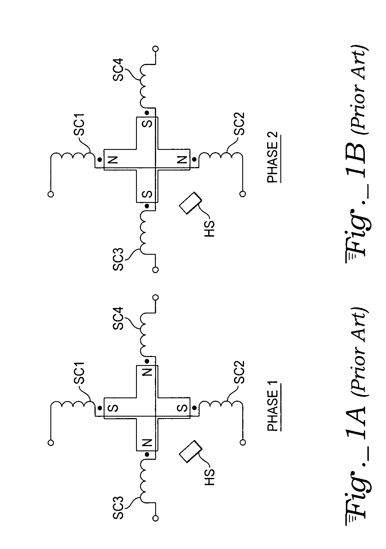
TECHNICAL FIELD [0001] The present invention relates to two-phase brushless DC motors, and in particular to rotor position sensing and commutation control for such motors. BACKGROUND ART [0002] Two-phase brushless DC (BLDC) motors are widely used in fans for ventilating and cooling central processing units (CPUs), graphics processors, power supplies, and many other applications. An advantage of the BLDC motors is that they, compared to brushed DC motors, are lighter, accelerate faster, produce little electrical or acoustical noise, and require no maintenance (no brush wearing). The requirements for cooling fans are continuously increasing as the use of powerful cooling-requiring electronics are increasing. As more fans are installed in more products, the need for low-cost fan solutions is evident to keep the overall cost of end-products low. Further, as the number of fans in homes and offices is increased, the need to keep these fans as quiet and efficient as possible is also gettin...

Claims


Application Information

Patent Timeline
IPC IPC(8): H02P7/50H01R39/46
CPCH02P6/182
Inventor LASSEN, JACOB L.
Owner ATMEL CORP
Learn More