Temporary absorbable venous occlusive stent and superficial vein treatment method

a technology of occlusive stent and superficial vein, which is applied in the field of superficial vein treatment methods, can solve the problems of prolonged recovery time, inconvenient operation, and need for hospitalization and surgery, and achieve the effects of reducing distension of varicose vein, fibrosis and vein collapse, and promoting localized blood clotting

Inactive Publication Date: 2006-08-24
TYCO HEALTHCARE GRP LP
View PDF99 Cites 58 Cited by
  • Summary
  • Abstract
  • Description
  • Claims
  • Application Information

AI Technical Summary

Benefits of technology

[0007] The foregoing problems are solved and an advance in the art is obtained by a novel temporary absorbable venous occlusive stent and a related varicose vein treatment method. The stent includes a stent body, a bio-absorbable material associated with the body, and a closure for blocking blood flow past the stent when implanted in a vein. The stent promotes localized blood clotting, fibrosis and vein collapse as the stent is absorbed. A permanent blockage is thereby produced that prevents the undesirable back flow of blood from above the stent implantation site, thereby reducing distension of the varicose vein below the implantation site.

Problems solved by technology

This technique suffers from the usual drawbacks associated with invasive procedures, i.e., the need for hospitalization and surgery under general anesthesia, associated pain, infection risk, prolonged recovery time, limited mobility during recovery, permanent scarring, etc.
However, there is a risk that the high radio frequency energy could damage tissue that surrounds the treated area if the procedure is not performed properly.
Moreover, the electronic equipment and procedural instrumentation required for the radio frequency technique are relatively costly.
There is also no way to readily confirm that the treatment has been effective without the use of a venogram requiring dye injection and X-ray imaging.

Method used


Image

  • Temporary absorbable venous occlusive stent and superficial vein treatment method
  • Temporary absorbable venous occlusive stent and superficial vein treatment method
  • Temporary absorbable venous occlusive stent and superficial vein treatment method

Examples


exemplary embodiment 2

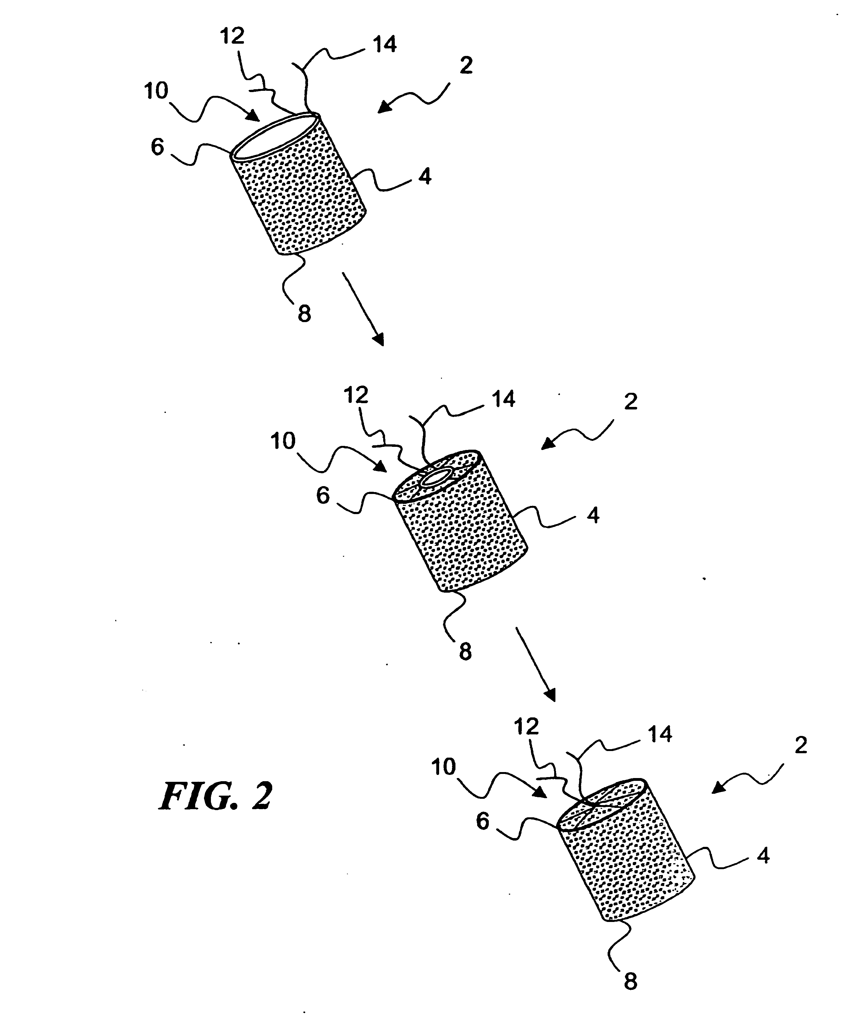
[0036]FIG. 2 illustrates a temporary absorbable venous occlusive stent that may be used in accordance with the invention. The stent 2 is configured as a generally tubular body 4 having a proximal end 6 and a distal end 8. The body 4 is made from a bio-absorbable material having the capability to absorb within a time frame that is long enough to allow the aforementioned permanent blockage to form in a vein to be implanted. By way of example only, a fabric woven from threads of dissolvable (e.g., polylactic acid) suture material could be used to form the body 4. Such material has an absorption schedule of about 28 days, which should be more than adequate for purposes of the present invention. Both ends of the stent 2 are initially open, but the proximal end 6 is provided with a suitable closure system that allows it to be closed following deployment.

[0037]FIG. 2 shows one exemplary closure system in the form of a drawstring arrangement. In particular, a drawstring 10 made from a disso...

exemplary embodiment 102

[0040]FIGS. 4A-4B and 5A-5B illustrate additional stent configuration alternatives. In FIG. 4A, a second exemplary embodiment 102 of a temporary absorbable venous occlusive stent is shown. As can be seen with additional reference to FIG. 4B, the stent 102 is configured as a generally tubular body 104 having a proximal end 106 and a distal end 108. The body 104 is similar to the body 4 of FIG. 2 except that the proximal end 106 of the body 104 has a closed end wall 110. The end wall 110 provides a closure system for the stent 102 that represents an alternative to the drawstring closure system used in the stent 2 of FIG. 2. Note that the end wall 110 can either be permanently formed as part of the body 104 or alternatively could be separately attached thereto, either prior to, during or after deployment of the stent 102 (e.g., as an insertable plug). Although the end wall 110 is located at the proximal end 106 of the stent 102, it could also be located at the distal end 108. A wall co...

exemplary embodiment 202

[0041] In FIG. 5A, a third exemplary embodiment 202 of a temporary absorbable venous occlusive stent is shown. As can be seen with additional reference to FIG. 5B, the stent 202 is configured as a generally solid cylindrical body 204 having a proximal end 206 and a distal end 208. The use of a solid body 204 provides a closure system for the stent 202 that represents an alternative to the drawstring closure system used in the stent 2 of FIG. 2. The body 204 can be made from any suitable bio-absorbable material, such as packed or bundled bio-absorbable filaments, folded bio-absorbable fabric, or a bio-absorbable foam. Although the body 204 is shown as being generally cylindrical, it will appreciated that other configurations could also be used, such as spheres, cones, pyramids, irregular shapes, etc., to implement a body portion of the stent 202.

[0042] Turning now to FIGS. 6A-6K, an exemplary stent implantation method utilizing pathways within a patient's deep vein system will now be...


PUM

PropertyMeasurementUnit
anatomical structureaaaaaaaaaa
bioabsorbableaaaaaaaaaa
frequencyaaaaaaaaaa

Abstract

A temporary absorbable venous occlusive stent for use in a varicose vein treatment method includes a stent body, a bio-absorbable material associated with the body, and a closure for blocking blood flow past the stent when implanted in a vein. The stent produces localized blood clotting, fibrosis and vein collapse as it is absorbed. A permanent blockage is produced that prevents the undesirable back flow of blood from above the blockage site, thereby reducing distension of a varicose vein below the blockage site.

Description

CROSS-REFERENCE TO RELATED APPLICATIONS [0001] This application is a continuation of U.S. patent application Ser. No. 10 / 754,919, filed Jan. 10, 2004, titled TEMPORARY ABSORBABLE VENOUS OCCLUSIVE STENT AND SUPERFICIAL VEIN TREATMENT METHOD, which claims the benefit under 35 U.S.C. § 119(e) of U.S. Provisional Patent Application Ser. No. 60 / 520,530, filed Nov. 17, 2003, titled TEMPORARY ABSORBABLE STENT. The entire disclosure of each of the above-noted prior application and the above-noted provisional application is hereby incorporated by reference herein and made a part of this specification.BACKGROUND OF THE INVENTION [0002] 1. Field of the Invention [0003] This invention relates to vascular disease and the treatment thereof. More particularly, the invention pertains to an apparatus and method for treating varicose veins. [0004] 2. Description of the Prior Art [0005] By way of background, the most common technique for treating varicose veins is to remove one or more superficial blo...

Claims


Application Information

Patent Timeline
Patent Type & Authority Applications(United States)
IPC IPC(8): A61F2/06A61B17/04A61B17/12A61B19/00A61F2/24A61L31/06A61L31/14
CPCA61B17/0467A61B17/12022A61B17/1204A61B17/12172A61B2019/5454A61L31/06A61L31/148C08L67/04A61B2017/12054A61B2090/3954
Inventor TAHERI, SYDE A.
Owner TYCO HEALTHCARE GRP LP
Why Eureka
Try Eureka