Device with needle penetrable and laser resealable portion and related method

Inactive Publication Date: 2006-08-31
MEDICAL INSTILL TECH
View PDF69 Cites 106 Cited by
  • Summary
  • Abstract
  • Description
  • Claims
  • Application Information

AI Technical Summary

Benefits of technology

[0008] In accordance with a first aspect, the present invention is directed to a device including a needle penetrable and laser resealable portion that is pierceable with a needle to form a needle aperture therethrough to fill a chamber of the device with a predetermined substance through the needle, and is laser resealable to hermetically seal the needle aperture by applying laser radiation at a predetermined wavelength and power thereto. The needle penetrable and laser resealable portion defines a predetermined wall thickness in an axial direction thereof, and includes a thermoplastic that s

Problems solved by technology

One of the drawbacks associated with such prior art dispensers, and processes and equipment for filling such dispensers, is that the filling process is time consuming, and the processes and equipment are expensive.
Further, the relatively complex nature of the filling processes and equipment can lead to more defectively filled dispensers than otherwise desired.
In many cases, there are complex assembly machines for assembling the vials or other dispensers that are located within the aseptic area of the filling machine that must be maintained sterile.
This type of machinery can be a significant source of unwanted particles.
In closed barrier systems, convection flow is inevitable and thus laminar flow, or substantially laminar flow, cannot be achieved.
When operation of an isolator is stopped, a media fill test may have to be performed which can last for several, if not many days, and can lead to repeated interruptions and significant reductions in production output for the pharmaceutical or other product manufacturer that is using the equipment.
In order to

Method used


Image

  • Device with needle penetrable and laser resealable portion and related method
  • Device with needle penetrable and laser resealable portion and related method
  • Device with needle penetrable and laser resealable portion and related method

Examples


Example

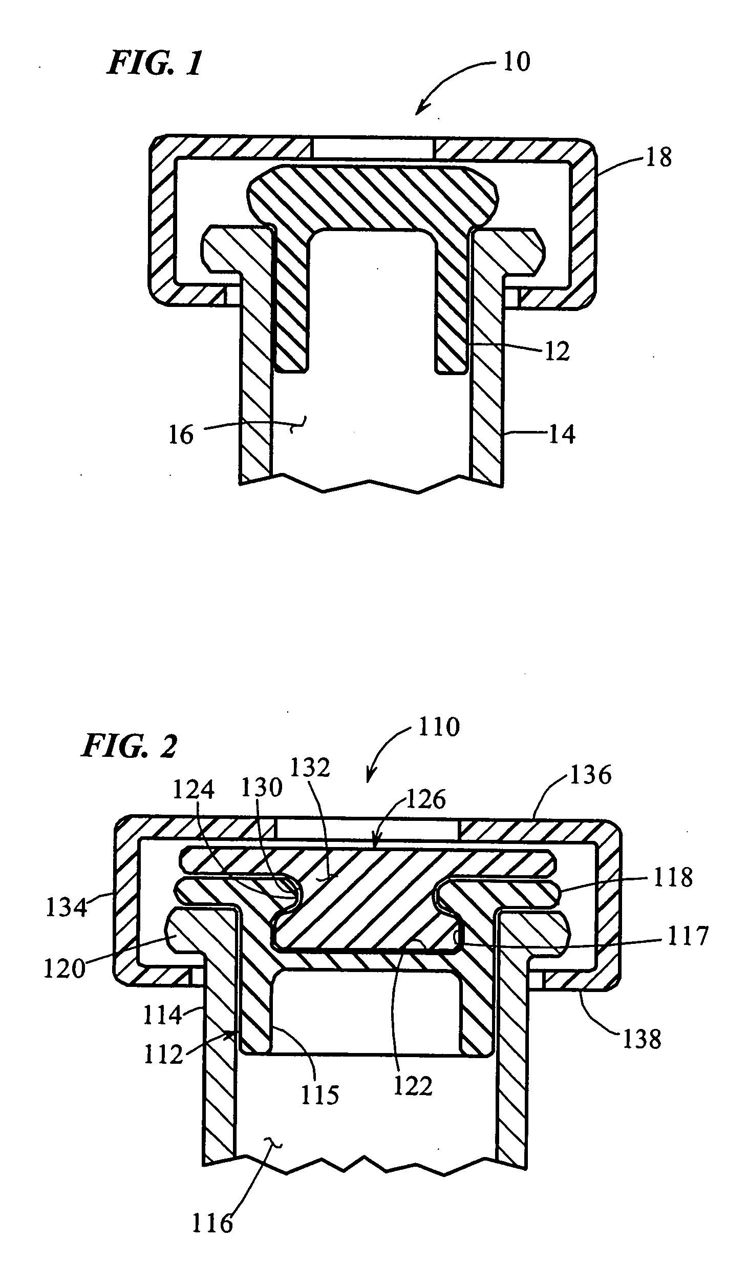
[0063] As shown in FIG. 1, a prior art cap for a medicament vial is generally designated by the reference numeral 10. The cap 10 includes a vulcanized rubber base 12, which is slidably received within the open end of a vial 14. The vial 14 is made of glass or like material, and it defines a chamber 16 for receiving medicament. An aluminum locking ring 18 surrounds the periphery of the cap 12 and vial 14, and it is crimped in place to lockably connect and seal the cap to the vial.

[0064] In operation, a hypodermic needle (not shown) is inserted through the vulcanized rubber base in order to deposit medicament within the chamber 16. Once the medicament has been deposited, the needle is withdrawn from the cap 10. Although the hole resulting from insertion of the needle will shrink somewhat from its maximum diameter due to the resiliency of the vulcanized rubber, the resultant hole is typically still large enough to pass gas or vapor and thereby compromise any preservative-free medicame...


PUM

PropertyMeasurementUnit
Fractionaaaaaaaaaa
Fractionaaaaaaaaaa
Fractionaaaaaaaaaa

Abstract

A device and method are provided for needle penetrating and filling a chamber with a predetermined substance, and laser resealing a resulting needle hole in the device. A needle penetrable and laser resealable portion of the device is pierceable with a needle to form a needle aperture therethrough to fill the chamber through the needle, and is laser resealable to hermetically seal the needle aperture by applying laser radiation at a predetermined wavelength and power thereto. The needle penetrable and laser resealable portion defines a predetermined wall thickness in an axial direction thereof, and includes a thermoplastic that substantially prevents the formation of particles released into the chamber from the needle penetrable and laser resealable portion during penetration by and withdrawal of the needle. The thermoplastic includes a predetermined amount of pigment that allows the thermoplastic to substantially absorb laser radiation at the predetermined wavelength, substantially prevent the passage of radiation through the predetermined wall thickness thereof, and hermetically seal a needle aperture formed in the needle penetration region thereof in a predetermined time period.

Description

CROSS-REFERENCE TO RELATED APPLICATIONS [0001] This patent application is a continuation of copending U.S. patent application Ser. No. 10 / 766,172, filed Jan. 28, 2004, entitled “Medicament Vial Having a Heat-Sealable Cap, and Apparatus and Method for Filling the Vial”, now U.S. Pat. No. 7,032,631, which is a continuation-in-part of U.S. patent application Ser. No. 10 / 694,364, filed Oct. 27, 2003, entitled “Medicament Vial Having A Heat-Sealable Cap, And Apparatus and Method For Filling The Vial”, now U.S. Pat. No. 6,805,170, which is a continuation of similarly titled co-pending U.S. patent application Ser. No. 10 / 393,966, filed Mar. 21, 2003, now U.S. Pat. No. 6,684,916, which is a divisional of similarly titled U.S. patent application Ser. No. 09 / 781,846, filed Feb. 12, 2001, now U.S. Pat. No. 6,604,561, which, in turn, claims the benefit of similarly titled U.S. Provisional Application Ser. No. 60 / 182,139, filed Feb. 11, 2000. Further, parent application Ser. No. 10 / 766,172 claim...

Claims


Application Information

Patent Timeline
IPC IPC(8): B65B1/04A61J1/14B65B3/00B65B57/02B65DB65D1/00B65D3/00B65D39/00B65D51/00
CPCA61J1/1406B29C66/542A61J2001/1468A61L2/08B29C65/16B29C65/1616B29C65/1619B29C65/18B29C66/001B29C66/342B29C66/534B29C67/004B29L2031/7158B29L2031/753B65B3/003B65B7/161B65D51/002A61J1/18B29C66/5344A61J1/2096B29C65/1677B29C65/1654B29C65/00A61J1/1468B29C66/8322B29C66/73755B29C66/7392B29C66/73921B29C66/7394B29C66/71B29C66/612B29C66/1222B29C66/1224B29C66/12461B29C66/1312B29K2025/08B29K2023/00
Inventor PY, DANIEL
Owner MEDICAL INSTILL TECH
Why Eureka
Try Eureka