Real-time infrared thermography inspection and control for automated composite material layup

a composite material and infrared thermography technology, applied in the direction of optical radiation measurement, instruments, image enhancement, etc., can solve the problems of excessive gaps, ineffective detection of resin or fiber, and laborious manual inspection to perform this task during layup, etc., to achieve the effect of small variations in the surface of the material

Active Publication Date: 2006-08-31
THE BOEING CO
View PDF6 Cites 119 Cited by
  • Summary
  • Abstract
  • Description
  • Claims
  • Application Information

AI Technical Summary

Benefits of technology

[0007] The foregoing needs are met, to a great extent, by the present invention, wherein in one aspect a method and apparatus are provided that in some embodiments perform real-time infrared thermal imaging of a composite material during an automated fabrication layup process and provide control signals to a fabrication device, which is not susceptible to machine vibrations, and is capable of detecting slight variations in material surface and subsurface characteristics.

Problems solved by technology

Manual inspection to perform this task during layup can be very labor intensive and problematic.
Many out of specification conditions such as excessive gaps, splices, resin or fiber cannot be effectively detected after cure by non-destructive techniques and must be prevented or detected for correction during layup.
However, machine clearance and the width of the material can make the desired lighting angle difficult or impossible to obtain.
Furthermore, this method is not successful in detecting non-adhered material or inclusions, which produce minimal changes in the composite material surface.
However, this method requires precise control of distance to and alignment with the material surface, making the method susceptible to vibrations during fabrication processes.
This method also is not successful in detecting non-adhered material or thin inclusions, which produce extremely small height variations.

Method used


Image

  • Real-time infrared thermography inspection and control for automated composite material layup
  • Real-time infrared thermography inspection and control for automated composite material layup
  • Real-time infrared thermography inspection and control for automated composite material layup

Examples


Embodiment Construction

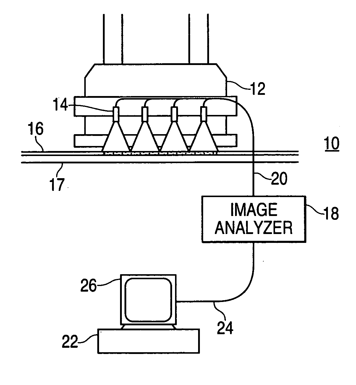
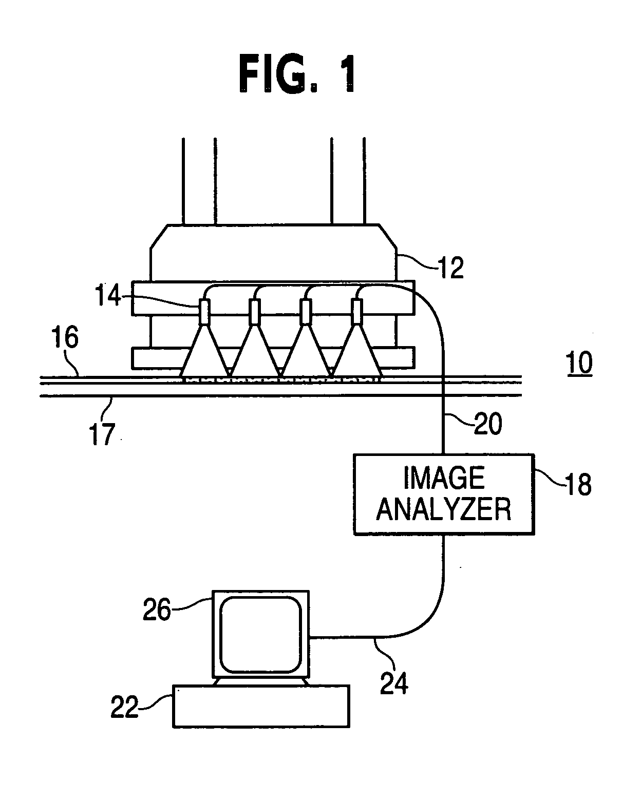
[0020] Infrared thermal imaging, also known as thermography or photothermal inspection, methods and devices make it possible to perform nondestructive testing of a material to detect defects, variations in the properties of the material, or differences in thickness of a coating or layer of the material. Infrared thermal imaging can detect local variations in thermal diffusivity or thermal conductivity at or beneath the surface of the material. Photothermal inspection can be used on metals, such as ferrous materials, including steel, or on non-metallic materials, such as plastics, ceramics, or composite materials.

[0021] Typically, the surface of the material is heated, for example with a laser or flash heating, and after a fixed period of time, a thermal image is taken of the surface of the material. An infrared camera images the infrared spectral radiance from the surface of the material, which is representative of the temperature of the surface of the material. Differences in temp...


PUM

PropertyMeasurementUnit
widthaaaaaaaaaa
widthaaaaaaaaaa
widthaaaaaaaaaa

Abstract

A real-time thermal imaging apparatus and method includes multiple digital infrared cameras mounted to an automated composite material layup device to record digital infrared images of the composite material surface on a real-time basis during a composite material layup process. The digital infrared cameras are triggered periodically to produce digital images of the composite material. The digital image data is sent to an image analyzer which detects edges of and anomalies in the composite material and generates alarm and other process control signals. The image analyzer also aggregates the digital images from the multiple cameras and the digital images recorded over a sequence in time to produce a continuous virtual digital image of the composite material surface. The digital image data and associated analysis results are saved and may be displayed on a real-time basis or at a later time.

Description

FIELD OF THE INVENTION [0001] The present invention relates generally to nondestructive in-process inspection or evaluation. More particularly, the present invention relates to infrared thermography inspection of composite materials during layup, prior to consolidation and cure. BACKGROUND OF THE INVENTION [0002] Graphite fiber reinforced epoxy composites are playing an important role in the production of critical aerospace structures and primary structures of commercial aircraft. These graphite / epoxy composite material products are often fabricated from resin-impregnated cloth, mat or filaments in flat form known as prepreg. After the initial fabrication, or layup, process composite materials generally are inspected to identify flaws in the composite material, as well as to verify that the material edges are within tolerance. [0003] For aerospace products made from composite materials it is important that flaws and out of tolerance conditions are prevented from entering the consoli...

Claims


Application Information

Patent Timeline
Patent Type & Authority Applications(United States)
IPC IPC(8): B32B38/00
CPCG01N25/72G06T7/0004G06T7/0083G06T2200/32G06T2207/10048G06T2207/20132G06T2207/30108B29C70/38B29C70/54G06T7/12
Inventor RITTER, JOHN A.SJOGREN, JOHN F.
Owner THE BOEING CO
Why Eureka
Try Eureka