
Resistive balance for an energy storage device

a technology of resistive balance and energy storage device, which is applied in the direction of cell components, cell component details, electrochemical generators, etc., can solve the problems of shortening the likely operating life of the device, degrading the short-term performance characteristics of the cell, and limiting the operating voltag

Inactive Publication Date: 2006-08-31
CAP XX LTD
View PDF3 Cites 73 Cited by
  • Summary
  • Abstract
  • Description
  • Claims
  • Application Information

AI Technical Summary

Benefits of technology

[0072] The above properties for a given cell are known to change with time, the temperature of a cell, and the voltage to which a cell is exposed. Accordingly, even for those cells that are thought to be well matched at the time of manufacture, they will not necessarily so remain as to cell is put into use. This is exacerbated by the fact that, for some of to properties referred to above, once a difference manifests sufficiently, it has the effect of increasing that difference.
[0073] By way of example, for a plurality of series connected supercapacitive cells, each of the cells has a unique equivalent parallel resistance (EPR) based upon its physical make up—including any impurities and its chemistry—for a given temperature and voltage across the call. If the cells in the series experience, during use, a temperature change this typically results in a change to the EPR which is unlikely to be the same for each cell. Accordingly, well matched cells are easily able to become poorly matched due to environmental influences such as temperature change, mechanical stresses, and the like. This effect is exacerbated where the cells in the series are subject to differentials in environmental effects. An instance of this occurs with stacked cells, where the cell on the bottom of the stack is preferentially heated due to its relative proximity to a heat source such as a processor or other circuitry or components.

Problems solved by technology

Typically, the limitations to the operating voltage are the properties of one or more of the following components used with a supercapacitor; the electrolyte salt; the electrolyte solvent; the electrode coating; the current collector; the separator; and the packaging.
However, prolonged exposure will usually degrade the short-term performance characteristics of the cell, as well as shortening its likely operating lifetime.
It is well recognised that batteries are good at storing energy but compromise design to enable high power delivery of energy.
It is also well recognised that conventional capacitors enable fast (high power) delivery of energy, but that the amount of energy delivered is very low—due to the low capacitance available.
However, this mode is periodically punctuated by the need to find the nearest base station and a signal is sent and received, requiring a higher load.
The problem with existing commercial capacitors using conventional materials is that their performance is limited by their dimensions.
However, water is susceptible to electrolysis to hydrogen and oxygen on charge and as such has a relatively small electrochemical window of operation outside of which the applied voltage will degrade the solvent.
However, in addition to the specific electrolyte requirements of supercapacitors mentioned above, there is also the practical consideration that supercapacitors do not operate in isolation.
Solvents which have high boiling points invariably have high viscosities, and consequently, low charge mobilities at low temperatures.
However, with those applications that require series combinations of supercapacitors additional complications arise.
Particularly, due to manufacturing tolerances—and the need to balance tolerances with cost—there inevitably arises a lack of uniformity between notionally like supercapacitors.
Matching nominally like cells or nominally like supercapacitors is typically based upon static and controlled conditions and, as such, is limited in effectiveness.
If the cells in the series experience, during use, a temperature change this typically results in a change to the EPR which is unlikely to be the same for each cell.
Accordingly, well matched cells are easily able to become poorly matched due to environmental influences such as temperature change, mechanical stresses, and the like.
This, in turn, will change the relative proportion of the application voltage that is seen by each cell and, hence, will increase the risk of failure of the cell that is seeing a higher proportion.
Even if the voltage seen by a cell does not approach the breakdown voltage of that cell, there is still the danger that it will exceed the operating voltage and thereby compromise the reliability and lifetime of the cell.

Method used


Image

  • Resistive balance for an energy storage device
  • Resistive balance for an energy storage device
  • Resistive balance for an energy storage device

Examples


Embodiment Construction

[0283] Energy storage cells used in supercapacitors are, like other electronic components, typically manufactured in high volumes. All high volume manufacture involves some compromises and the acceptance of tolerances in key characteristics of the devices being manufactured. This is no different for supercapacitive cells.

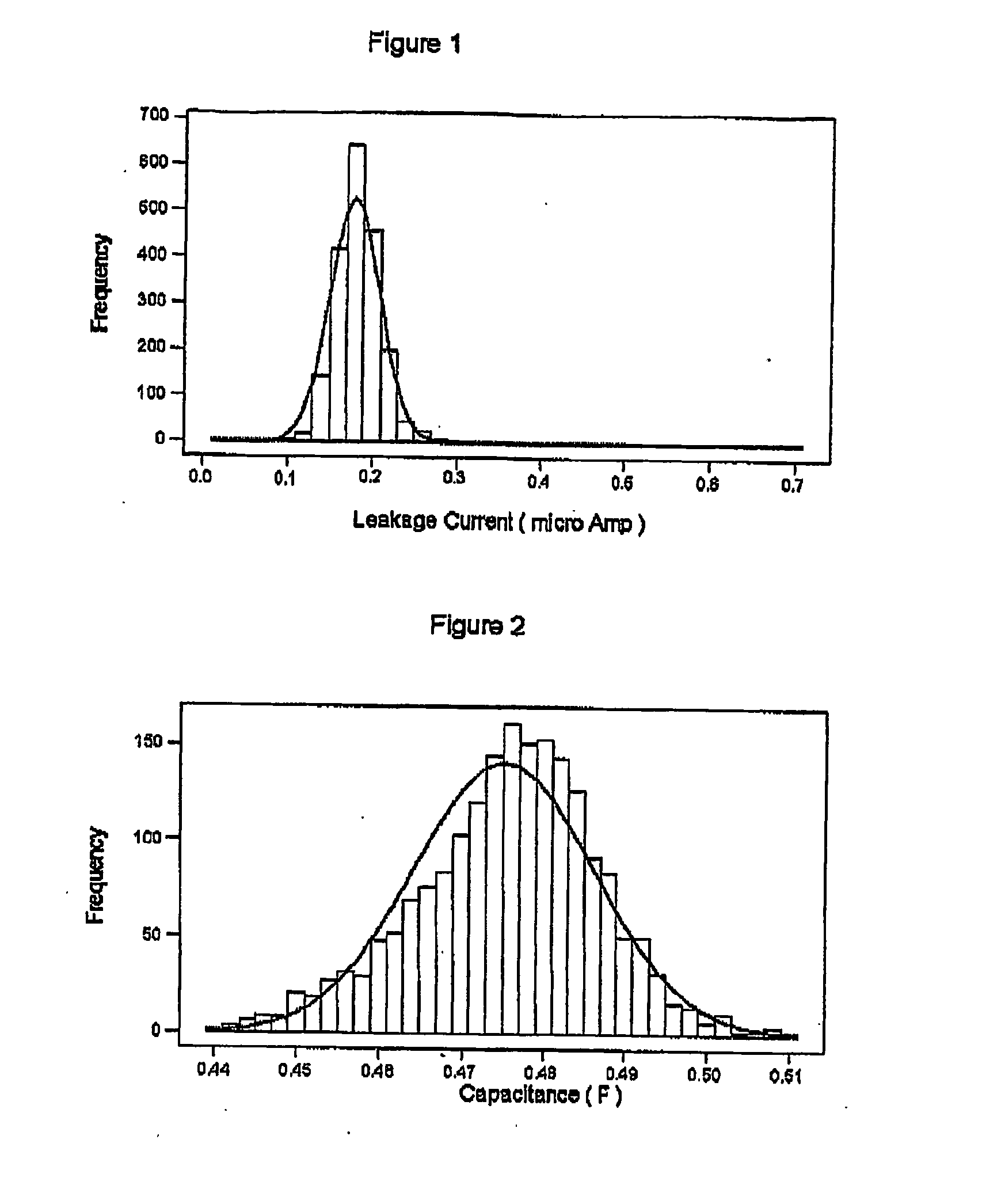
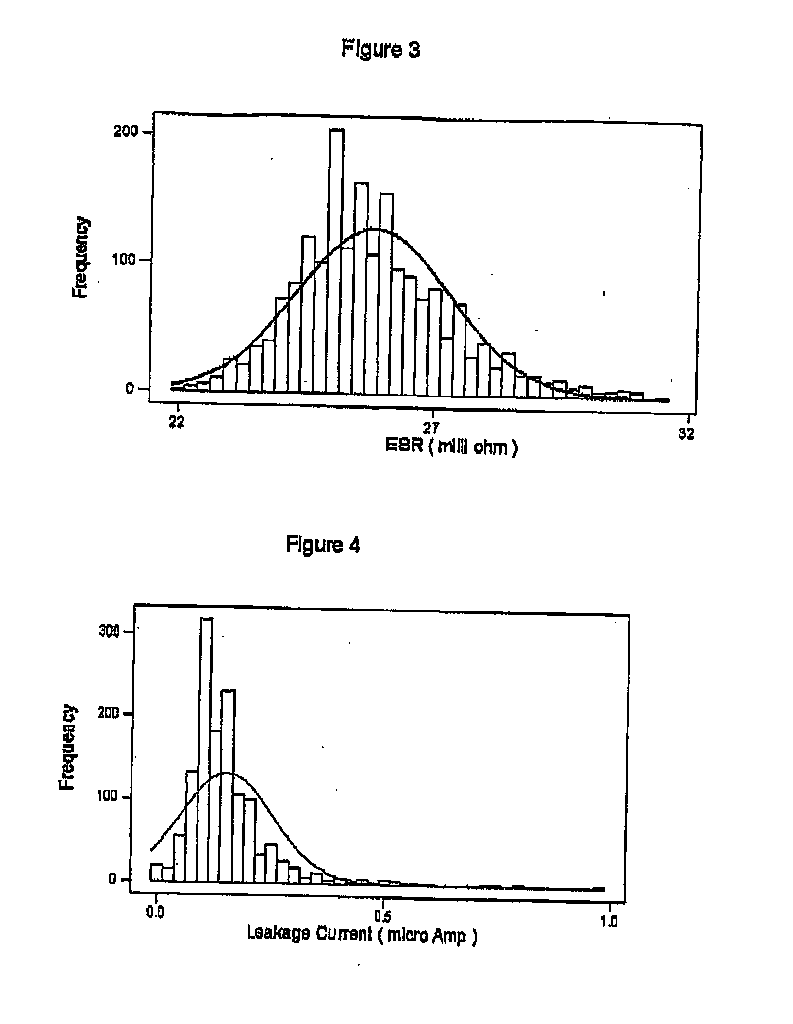
[0284] Referring to FIGS. 1 to 6, there are provided respective histograms that illustrates the distribution of various parameters of batches of mass produced notionally like cells for use in supercapacitors. It will be appreciated that while the distributions shown in the figures are typical, variations will arise between batches depending upon a variety of factors, including manufacturing vagaries and sample sizes. There will be similar distributions for other performance parameters. While some of these parameters are more economical to control within tighter tolerances than others, exact correspondence is neither expected nor achievable.

[0285] When matching cal...


PUM

PropertyMeasurementUnit
thickaaaaaaaaaa
voltageaaaaaaaaaa
thicknessaaaaaaaaaa

Abstract

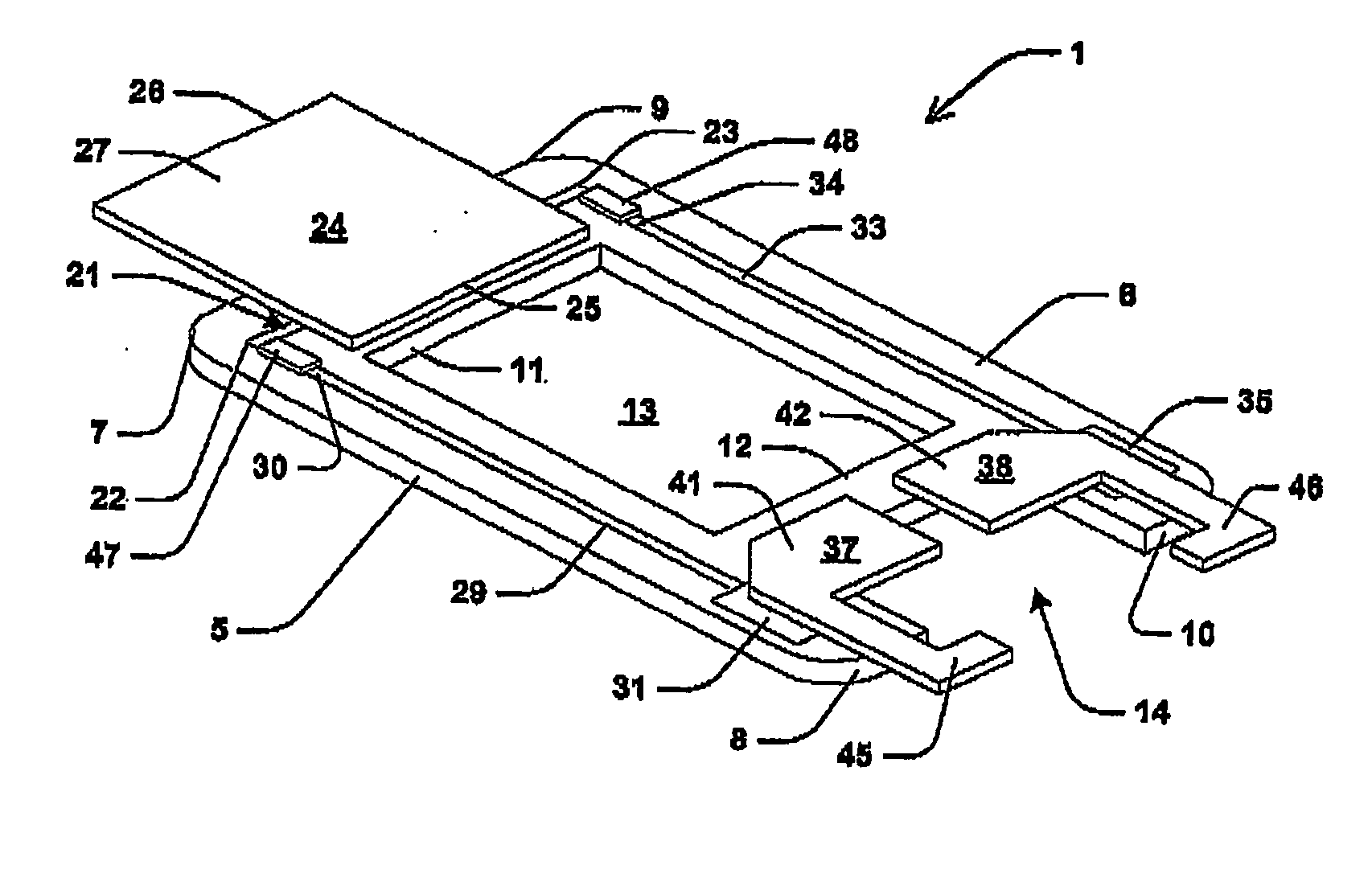
A resistive balance (1) for an energy storage device in the form of a supercapacitor (2). The supercapacitor has two energy storage cells (3, 4). In some embodiments, the balance is disposed intermediate the cells. Balance (1) includes two parallel, spaced apart and co-extensive longitudinal members (5, 6) that respectively extend between ends (7, 8) and ends (9, 10). Two parallel, spaced apart and co-extensive transverse members (11, 12) extend between members (5, 6). While member (11) is attached to members (7, 8) immediately adjacent to ends (7, 9) respectively, member (12) is attached to members (7, 8) adjacent to but spaced inwardly from respective ends (8, 10).

Description

FIELD OF THE INVENTION [0001] The present invention relates to a resistive balance and in particular to a resistive balance for an energy storage device. [0002] The invention has been developed primarily for use with a supercapacitor and will be described hereinafter with reference to that application. However, the invention is not limited to that particular field of use and is also suitable for other energy storage devices such as capacitors, fuel cells, primary batteries, secondary batteries, hybrids of these devices and the like. [0003] The terms “supercapacitor” and “supercapacitors”, as used in this specification, are intended to encompass electric double layer capacitors, hybrid devices including such capacitors, and similar energy storage devices. Supercapacitors are also referred to as ultracapacitors, electrochemical capacitors, double layer capacitors or the like. DISCUSSION OF THE PRIOR ART [0004] Any discussion of the prior art throughout the specification should in no w...

Claims


Application Information

Patent Timeline
Patent Type & Authority Applications(United States)
IPC IPC(8): H01M2/24H01M50/529H01G9/155H01G9/28H01M50/51H01M50/516H02J7/00
CPCH01M2/202H02J7/0016Y02T10/7055Y02T10/70Y02E60/10H01M50/516H01M50/51
Inventor KESHISHIAN, SARKISTURNER, GEOFFREY ALANPAUL, GEORGE LANGEDRUMMOND, CALUM JOHN
Owner CAP XX LTD
Learn More