Exhaust gas purification system of an internal combustion engine and method for purifying the exhaust gases thereof

a technology of exhaust gas purification system and internal combustion engine, which is applied in the direction of engines, machines/engines, mechanical equipment, etc., can solve the problems of insufficient activity of the known scr system at exhaust gas temperatures below approximately 250° c., and achieve the reduction of nox emissions, nox reduction, and nox reduction

Inactive Publication Date: 2006-09-07
ROBERT BOSCH GMBH
View PDF10 Cites 21 Cited by
  • Summary
  • Abstract
  • Description
  • Claims
  • Application Information

AI Technical Summary

Benefits of technology

[0005] An exhaust gas purification system in accordance with the present invention includes at least one oxidation catalytic converter disposed in an exhaust gas duct of an internal combustion engine, and at least one device for selective catalytic reduction of the exhaust gases, which device is installed downstream of the oxidation catalytic converter. The exhaust gas purification system further includes a feed device for feeding reducing agent into the exhaust gas stream and admixing it therewith upstream of the device, or in the device, for selective catalytic reduction (SCR catalytic converter). According to the invention, the exhaust gas purification system has a switch-over device and/or a further feed device for selectively feeding reducing agent into the exhaust gas stream upstream of, or inside,

Problems solved by technology

The insufficient activity of the known SCR system at exhaus

Method used


Image

  • Exhaust gas purification system of an internal combustion engine and method for purifying the exhaust gases thereof
  • Exhaust gas purification system of an internal combustion engine and method for purifying the exhaust gases thereof
  • Exhaust gas purification system of an internal combustion engine and method for purifying the exhaust gases thereof

Examples


Embodiment Construction

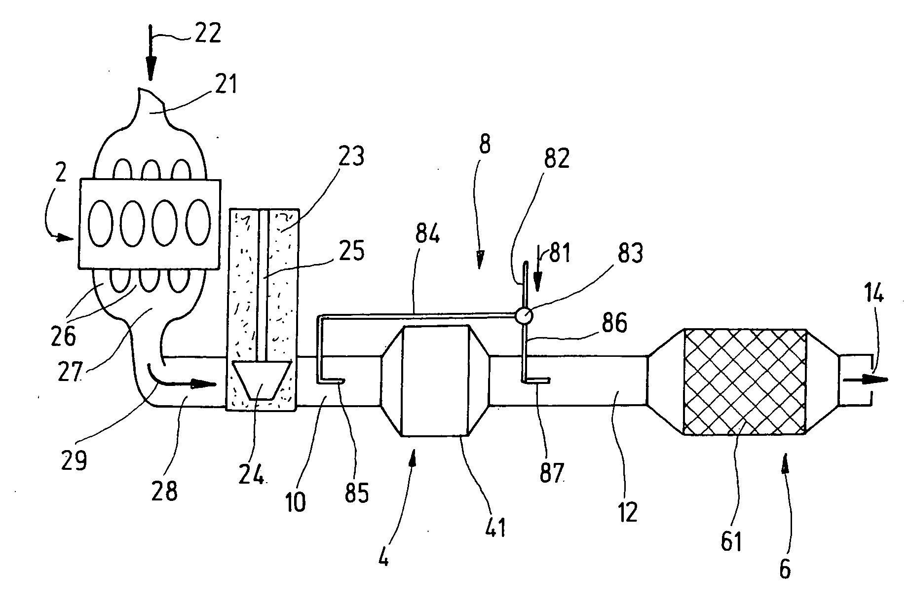
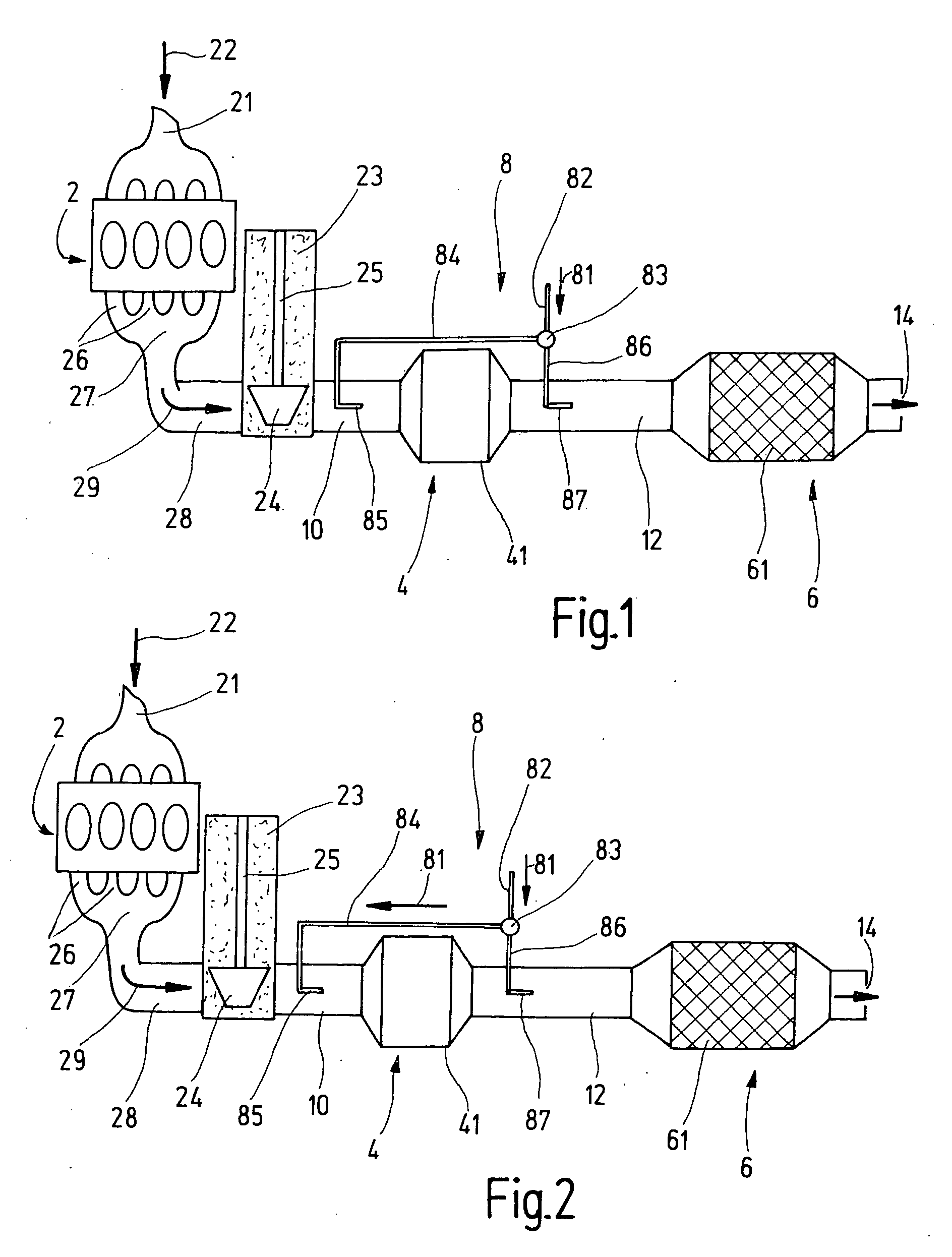
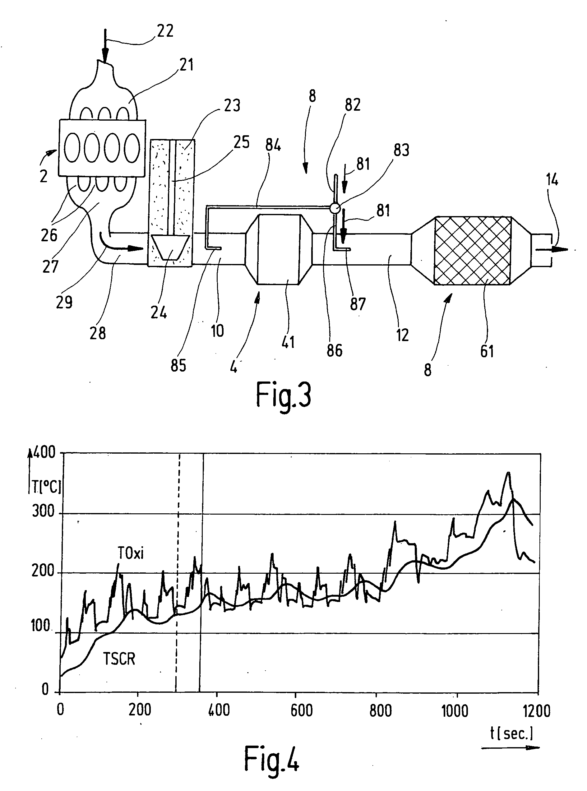
[0026]FIG. 1 shows an exhaust gas purification system according to the present invention. In FIG. 1, an oxidation catalytic converter 4 and a device for selective catalytic reduction, referred to as SCR catalytic converter 6, are disposed in an exhaust gas duct 28 of an internal combustion engine 2. Internal combustion engine 2 has an intake duct 21 for supplying fresh mixture 22, and outlet ducts 26 which are combined in a manifold 27 to form exhaust gas duct 28. Disposed in the exhaust gas duct is an exhaust gas turbine 24 of an exhaust gas turbocharger 23, which turbine 24 is coupled via a shaft 25 to a compressor, not shown here. Exhaust gas turbocharger 23 is optional and serves to improve the performance and exhaust gas emission characteristics of internal combustion engine 2.

[0027] Internal combustion engine 2 may be a diesel internal combustion engine featuring auto-ignition or a gasoline engine featuring direct fuel injection. Both types of engine emit a relatively oxygen-...


PUM


Abstract

An exhaust gas purification system for purifying the exhaust gas of an internal combustion engine, especially an internal combustion engine featuring auto-ignition and/or direct fuel injection, is provided. The system includes at least one oxidation catalytic converter disposed in an exhaust gas duct of the internal combustion engine, at least one device for selective catalytic reduction of the exhaust gases which is installed downstream of the oxidation catalytic converter, and a feed device for feeding reducing agent into the exhaust gas stream upstream of, or in, the device for selective catalytic reduction. A switch-over device is provided for selectively feeding reducing agent into the exhaust gas stream upstream of, or inside, the at least one oxidation catalytic converter. A corresponding method for purifying the exhaust gas of an internal combustion engine is also provided.

Description

FIELD OF THE INVENTION [0001] The present invention relates to an exhaust gas purification system of an internal combustion engine having a device for selective catalytic reduction, and relates particularly to a method for purifying exhaust gases of an internal combustion engine, in which an exhaust gas stream is passed through a device for selective catalytic reduction. BACKGROUND INFORMATION [0002] To lower the nitrogen oxide content of oxygen-rich exhaust gas, such as that emitted by diesel internal combustion engines and by internal combustion engines featuring direct gasoline injection, it is known to introduce a reducing agent into an exhaust tract. A suitable reducing agent is, for example, NH3, which may be introduced as a gas into the exhaust gas stream. In such so-called selective catalytic reduction (SCR), the ammonia is selectively reacted with the nitrogen oxides present in the exhaust gas to form molecular nitrogen and water. [0003] The insufficient activity of the kno...

Claims


Application Information

Patent Timeline
IPC IPC(8): F01N5/04F01N3/00F01N3/021F01N3/035F01N3/20F01N13/02F02B37/00
CPCF01N3/021F01N3/035F01N3/2066F01N3/36F01N2250/02F01N2610/14F02B37/00Y02T10/24F01N13/009Y02T10/12
Inventor RIPPER, WOLFGANGSCHALLER, JOHANNESLUEDERS, HARTMUTWALZ, CHRISTIANMAYER, THORSTEN
Owner ROBERT BOSCH GMBH
Why Eureka
Try Eureka