Elevated bus rapid transit system

Inactive Publication Date: 2006-09-07
STROMBERG DALE MARIE
View PDF11 Cites 42 Cited by
  • Summary
  • Abstract
  • Description
  • Claims
  • Application Information

AI Technical Summary

Benefits of technology

[0020] The present invention enjoys many useful advantages over existing low capacity rapid bus systems and intermediate capacity, light rail, rapid transit systems. The system's uniqueness is best characterized by its ability to follow the same route as a surface bus from the suburbs to the downtown and back, yet carry considerably more passengers per hour with less trip time than a road bound rapid bus system. Furthermore, the invention can carry the same hourly capacity as a light rail system separated from road traffic, without requiring a dedicated right-of-way, highway type thoroughfare, or existing railroad right-of-way for track structures, passenger platforms, and stationhouse as this invention is designed to be built in the motor vehicle lane of a typical four, six, or more lane road.
[0021] In a preferred embodiment, the high capacity elevated rapid bus of the present invention travels above utilities such as traffic signals, electrical wires, and streetlights three to four storeys above the road traffic. The infrastructure supporting the passenger vehicles and housing the movable platforms for passenger loading and

Problems solved by technology

The elevated rail and monorail systems of prior art do not solve the problems of constructing the trackway and elevated passenger loading platforms in a city stre

Method used


Image

  • Elevated bus rapid transit system
  • Elevated bus rapid transit system
  • Elevated bus rapid transit system

Examples


Example

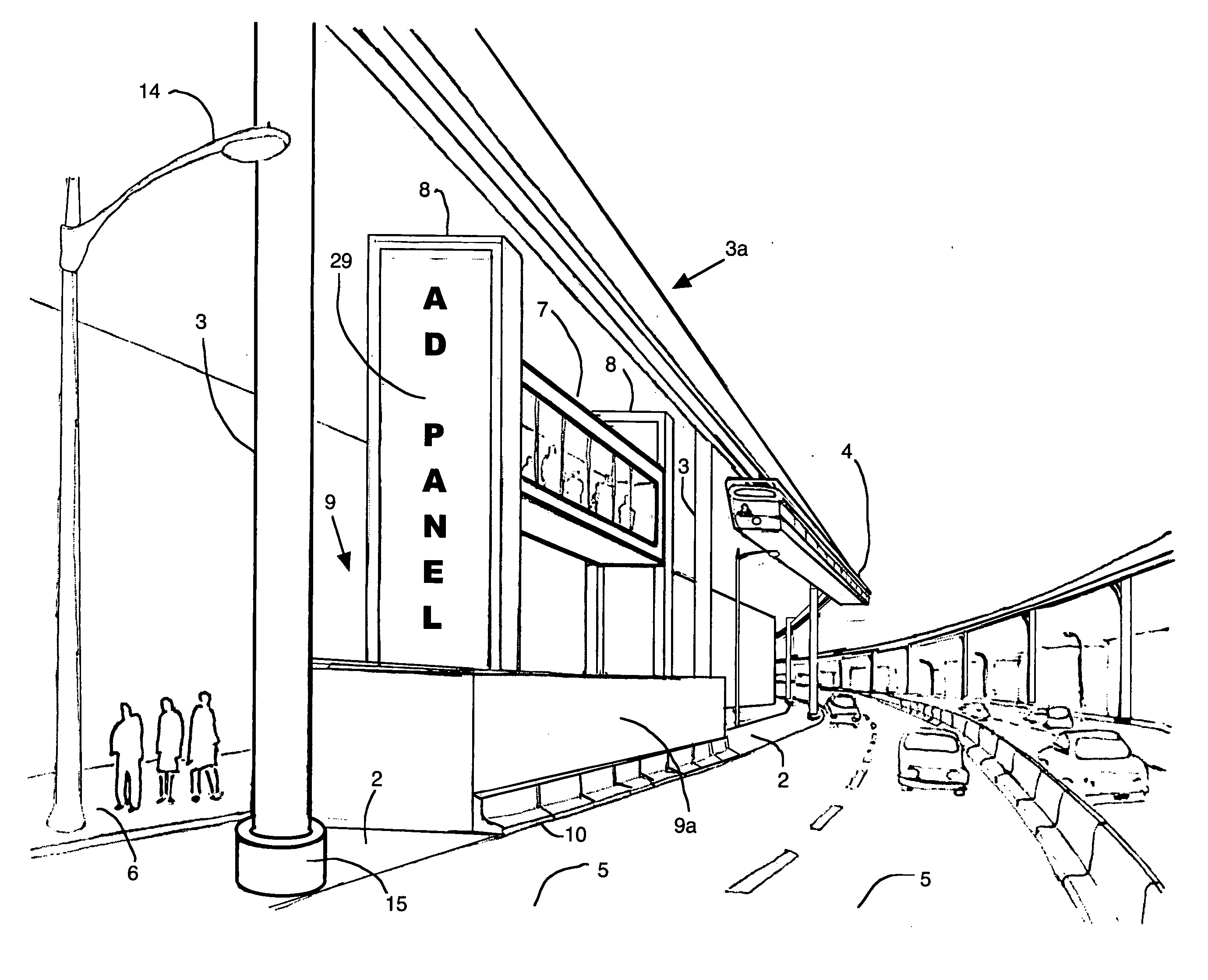
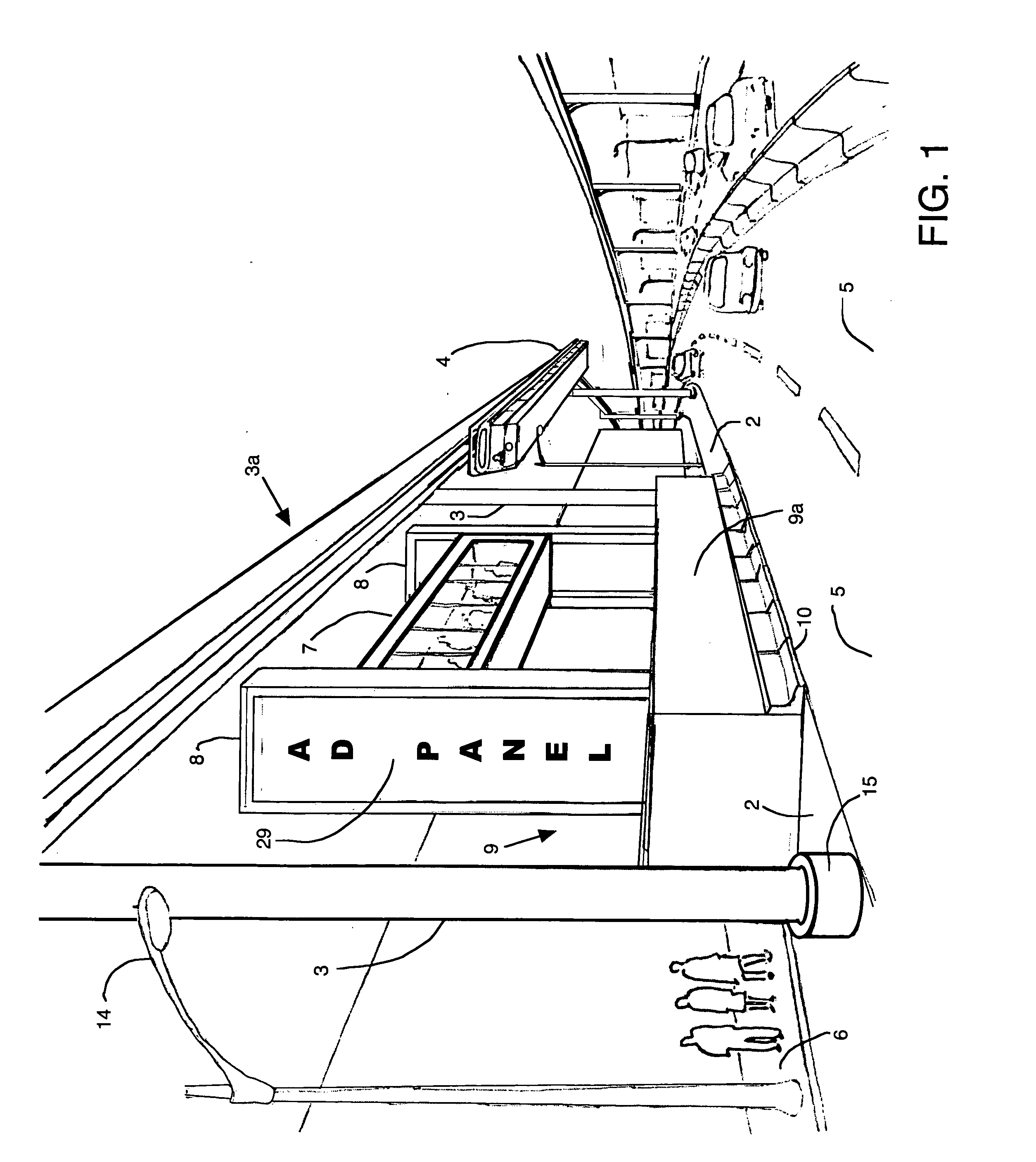
[0033] Referring to FIG. 1, there is shown a preferred embodiment of the high capacity elevated rapid bus system according to the present invention useful in increasing the hourly passenger capacity and decreasing the passenger trip time of a public transit bus route. The bus system is positioned in an existing motor vehicle road lane, preferably curb lane 2, which is often already dedicated to parking and / or used as a priority bus lane of a city street. Curb lane 2 is used to anchor support structures 3 in the form of a plurality of space support columns that suspend an elevated guideway 3a above the level of the street in a cantilevered configuration. An elevated bus 4 for carrying passengers is movable along the elevated guideway 3a above a road lane 5 on which normal vehicular traffic moves. Elevated bus 4 is shown suspended beneath elevated guideway 3a in FIG. 1, and is preferably suspended over the road traffic lane 5 adjacent to the parking and / or curb lane 2 next to the publ...


PUM


Abstract

An elevated public transit bus system that increases the passenger capacity and decreases the passenger trip time of a fixed route bus service traveling in traffic on a city street to provide a high capacity rapid transit system. The high capacity buses are suspended above the motor vehicle traffic lanes by a support structure constructed in the lane adjacent to the public sidewalk. The propulsion system of the electrically powered buses run in a box beam from which the transit passenger cabins are suspended. The beams guide the buses along the existing fixed route service that is being upgraded to the carrying capacity of an elevated rail rapid transit system. The bus stops or lift stations of the elevated buses for passenger pick up and drop off is also constructed in the road lane next to the sidewalk. The lift stations house an enclosed movable platform that lifts passengers from sidewalk level to the floor level of the suspended bus. The high capacity rapid bus system makes efficient use of city streets by significantly increasing the capacity of persons per lane per hour use over that of the private vehicle. This public transportation enhancement reduces traffic congestion, energy consumption, and air pollution by making bus service more attractive, and by increasing the capacity of the street to carry more transit users without taking away business dependant road parking spaces or public sidewalk space.

Description

FIELD OF THE INVENTION [0001] This invention relates to the public transportation urban transit industry and specifically to a city rapid bus system capable of attaining a higher hourly passenger capacity and which is similar to elevated urban rail rapid transit systems. BACKGROUND OF THE INVENTION [0002] Over the past three decades public transit bus systems have been losing market share of commuter trips to the private motor vehicle, which in turn contributes to traffic congestion, air pollution, and energy consumption in large urban areas. [0003] In order to make bus service more efficient and attractive many cities have reserved the motor vehicle lane of a street adjacent to the pedestrian walk (sidewalk) exclusively for buses in an express bus system. This lane is often referred to as the curb lane, and is used as a bus priority lane in the morning and evening rush hours. During the remainder of the day, the lane may be open to all traffic or reserved as parking lane for privat...

Claims


Application Information

Patent Timeline
IPC IPC(8): B61B1/00
CPCB61B1/02B61B3/02
Inventor STROMBERG, RONALD E.
Owner STROMBERG DALE MARIE
Why Eureka
Try Eureka