Deployment of different physical layer protocols in a radio access network

a radio access network and physical layer technology, applied in the field of different physical layer protocols in the radio access network, can solve the problems of increasing management complexity, increasing management complexity, and potential incompatibility

Inactive Publication Date: 2006-09-07
NOKIA CORP
View PDF19 Cites 19 Cited by
  • Summary
  • Abstract
  • Description
  • Claims
  • Application Information

AI Technical Summary

Benefits of technology

[0068] According to an embodiment of the second aspect of the present invention, said fifth protocol is an IEEE 802 MAC protocol, said sixth protocol is an ATM protocol, said seventh protocol is an AAL5 protocol, said eighth protocol is an IP protocol, and said ninth protocol is a TCP protocol. Said Transport Control Protocol (TCP) is defined by IETF RFC793 and provides a reliable stream delivery and virtual connection service to applications through the use of sequenced acknowledgment with retransmission of packets when necessary.

Problems solved by technology

However, with increasing numbers of transmission links (and correspondingly increasing numbers of cables and interfaces), the management complexity increases, and furthermore, compatibility problems may arise due to increasing ATM and IMA complexity.
The same problem is encountered in the context of a distributed base station architecture, as for instance specified by the Open Base Station Architecture Initiative (OBSAI) or the Common Public Radio Interface (CPRI).
Because on said Iub interface, again SDH / PDH links are most frequently used as transmission links, the same problems of increasing management complexity and potential incompatibility with increasing transmission capacity is encountered as in the case where a non-distributed base station is used.
Furthermore, due to the high data rate on the interface between the base station head and the base station body of a distributed base station, which is caused by the fact that the base band processing is performed in the base station body, a fibre connection may have to be used for this interface.
The fibre cable has to be installed by the operator, which vastly increases the deployment costs.

Method used


Image

  • Deployment of different physical layer protocols in a radio access network
  • Deployment of different physical layer protocols in a radio access network
  • Deployment of different physical layer protocols in a radio access network

Examples


first embodiment

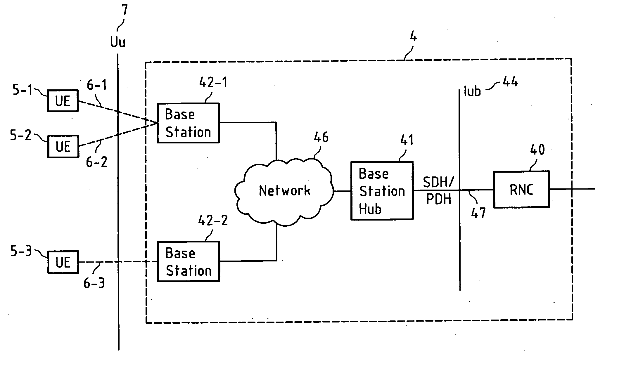
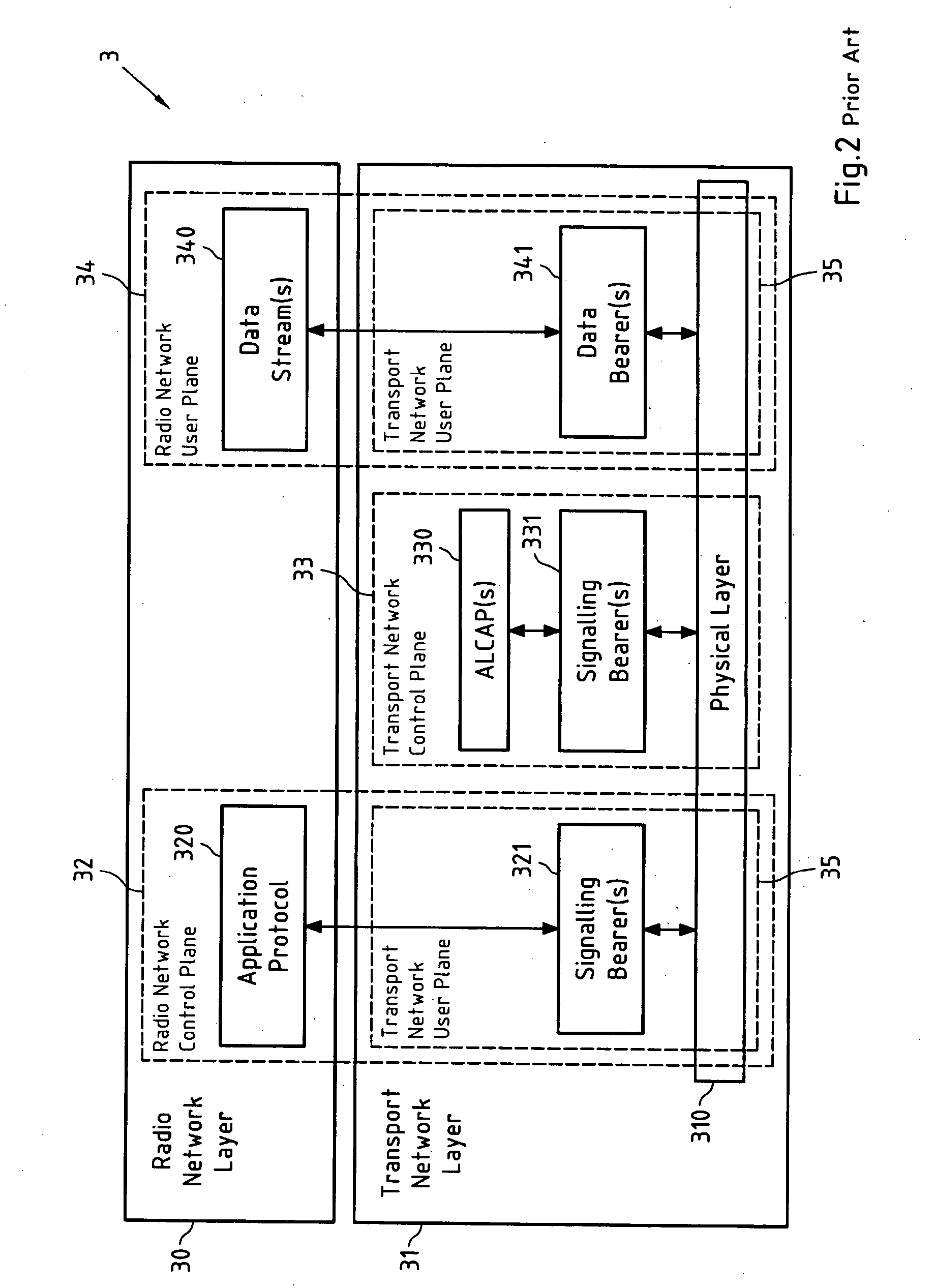
[0133]FIG. 5a depicts a first exemplary user plane protocol architecture 50 for the transmission of data streams 340 (see FIG. 2) over data (or transport) bearers 341 in the user plane 34 of a UTRAN according to the first embodiment of the present invention. Therein, said data streams 340 contain data from applications running on the top-most layer of the protocol architecture, for instance speech, and consist of a plurality of Frame Protocol (FP) frames. The data streams are transmitted between a base station (for instance the base station 42-1 of FIG. 4) and an RNC (for instance the RNC 40 of FIG. 4) via a base station hub (for instance the base station hub 41 of FIG. 4).

[0134] According to the first embodiment of the present invention, the ATM protocol 50-2 operated between the RNC and the base station for the transmission of user plane data streams 340 is not terminated in the base station hub. The FP frames are converted into ATM cells by the AAL2 protocol layers, i.e. AAL2 SS...

second embodiment

[0143]FIG. 6a depicts a user plane protocol architecture 60 for the transmission of data streams 340 (see FIG. 2) over data (or transport) bearers 341 in the user plane 34 of a UTRAN according to the second embodiment of the present invention. Therein, it is readily seen that the AAL2 CPS protocol 60-4 operated between the RNC and the base station is not terminated by the base station hub, so that AAL2 CPS packets are transmitted over the Ethernet network. This can be achieved with a transport layer 60-2 above the IEEE 802.3 MAC layer 60-1, which may for instance be implemented by using a proprietary header or even IP / UDP.

[0144] In the base station hub, this transport layer is then interworked with the ATM layer 60-3 used on top of the PDH / SDH physical layer protocol 47 operated between the RNC and the base station hub (see the left side of the protocol architecture 60). This may be achieved by a mapping table, which maps ATM interface parameters, VPIs, VCIs and CIDs into MAC addre...

third embodiment

[0158]FIG. 7a depicts a user plane protocol architecture 70 for the transmission of data streams 340 (see FIG. 2) over data (or transport) bearers 341 in the user plane 34 of a UTRAN according to the third embodiment of the present invention. In this user plane protocol architecture 70, the FP protocol 70-7 operated between the RNC and the base station is not terminated by the base station hub.

[0159] According to this third embodiment of the present invention, the FP frames can be transported on top of a proprietary multiplexing layer that interfaces with the IEEE 802.3 MAC layer 70-1 residing on top of an IEEE 802.3 physical layer protocol 46, or can be transported on top of a UDP / IP protocol architecture 70-2, 70-3, as it is depicted in FIG. 7a. The base station hub then terminates the UDP layer 70-3 towards the base station and the AAL2 SSSAR layer 70-6 towards the RNC. Therein, the AAL2 SSSAR layer 70-6 resides on top of the AAL2 CPS layer 70-5, which in turn resides on top of ...


PUM


Abstract

This invention relates to a method, a system, a base station, a base station hub (41) and software applications for data transmission between at least one base station (42-1, 42-2) and a radio network controller (40) in a radio access network, said method comprising operating a first-type physical layer protocol (46) for a transmission of said data between said at least one base station (42-1, 42-2) and a base station hub (41); operating a second-type physical layer protocol (47) for a transmission of said data between said base station hub (41) and said radio network controller (40); wherein said data comprises user data (340) that is transmitted between said radio network controller (40) and said at least one base station (42-1, 42-2) via said base station hub (41); and wherein said at least one base station (42-1, 42-2) performs at least base band processing for signals that are transmitted via a radio interface (7) and represent said user data (340).

Description

FIELD OF THE INVENTION [0001] This invention relates to a method, a system, a base station, a base station hub and software applications for data transmission between at least one base station and a radio network controller in a radio access network. BACKGROUND OF THE INVENTION [0002] The Universal Mobile Telecommunications System (UMTS) is a third-generation broadband wireless transmission system for text, digitized voice, video, and multimedia at data rates up to 2 megabits per second that offers a consistent set of services to mobile computer and phone users. [0003] The network elements of a UMTS 1 are illustrated in FIG. 1. The network elements are functionally grouped into the radio access network (UMTS Terrestrial Radio Access Network, UTRAN) 11 that handles all radio-related functionality, and the Core Network (CN) 12, which is responsible for switching and routing calls and data connections to external networks 2, for instance circuit-switched networks 20 such as PSTN and IS...

Claims


Application Information

Patent Timeline
Patent Type & Authority Applications(United States)
IPC IPC(8): H04Q7/00H04Q7/24H04J3/16H04J3/22H04W80/04H04W88/06H04W92/12
CPCH04W88/06H04L12/5601H04L2012/5607H04L2012/5625H04L2012/5656H04L2012/5658H04W80/04H04W92/12
Inventor MAJOR, TAMASMUSIOL, TORSTENKARPPINEN, PEKKAHAKKINEN, HANNUVAITOVIRTA, HANNU
Owner NOKIA CORP
Why Eureka
Try Eureka