Combustion system with recirculation of flue gas

a combustion system and flue gas technology, applied in the field of combustion fuels, can solve the problems of increasing the flow rate of the produced flue gas, lowering the temperature of combustion, and increasing the amount of excess air that is rejected into the atmosphere by the flue gas,

Inactive Publication Date: 2006-09-07
KALINA POWER LTD
View PDF20 Cites 34 Cited by
  • Summary
  • Abstract
  • Description
  • Claims
  • Application Information

AI Technical Summary

Benefits of technology

[0015] The present invention provides a method for utilizing combustion gases or flue gases as a heat source for a power system or other system requiring thermal energy, where the method includes the steps of supplying a stream comprising air and a first cooled recycled flue gas stream to a combustion chamber having an air inlet, a fuel inlet and a flue gas outlet. A hot combustion gas or flue gas stream is then mixed with a second cooled recycled flue gas stream to form a heat transfer stream. The heat transfer stream is then brought into a ...

Problems solved by technology

This excess air results in a lowering of the temperature of combustion.
However, the greater the excess of air, the greater the flow rate of the produced flue gases.
Because the flue gas cannot be cooled to a temperature equal to the initial temperature of the supplied air, the quantity of heat rejected into the atmosphere by the flue gas increases with increasing amounts of excess air.
This results in a reduction of the efficiency of the combustion system.
These systems are, perforce, expensive and complex structures that require a high degree of maintenance, especially due to the fact that the waterwall tubes are subjected to very high thermal stresses.
But in such a case...

Method used


Image

  • Combustion system with recirculation of flue gas
  • Combustion system with recirculation of flue gas
  • Combustion system with recirculation of flue gas

Examples


Embodiment Construction

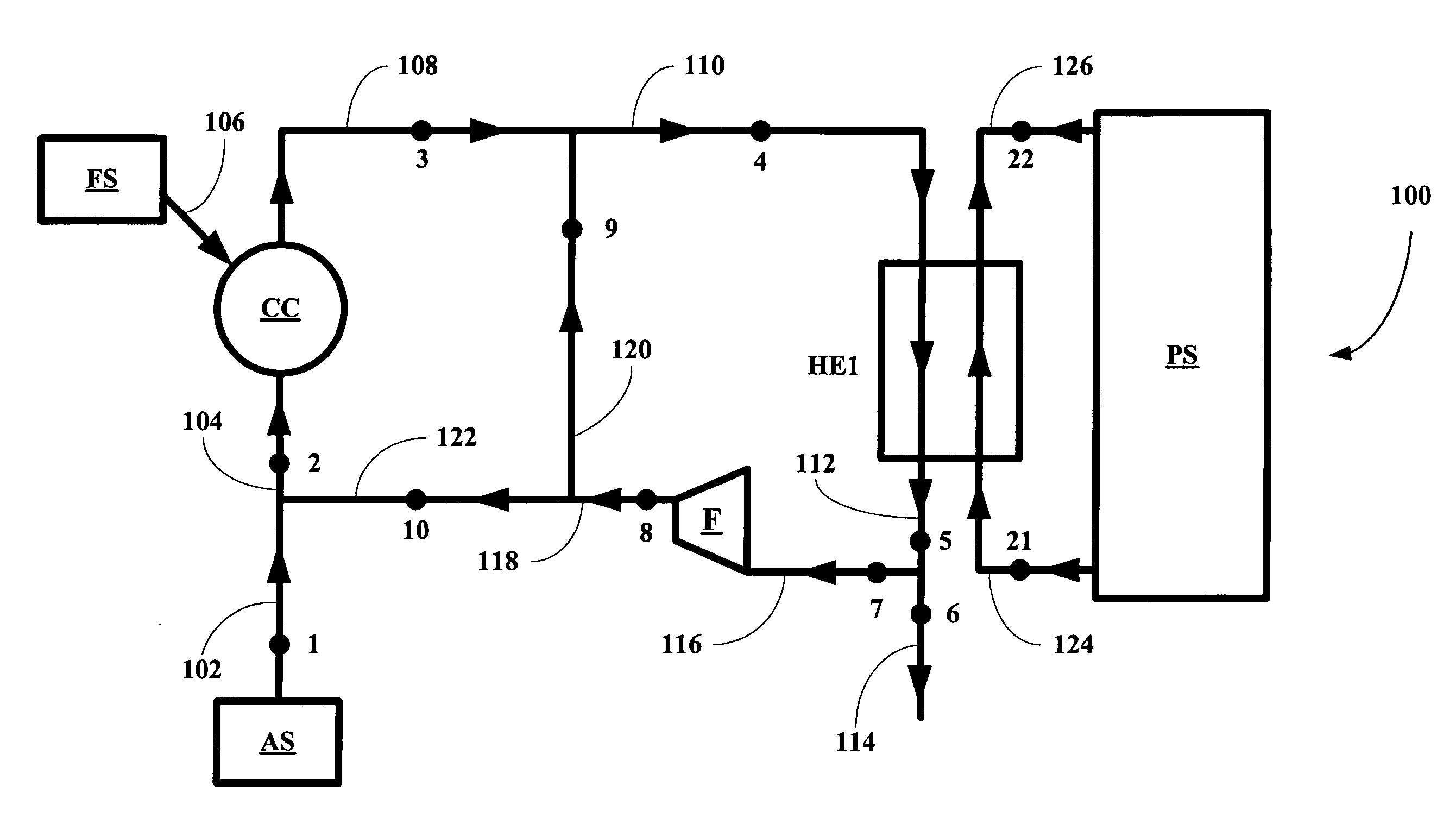
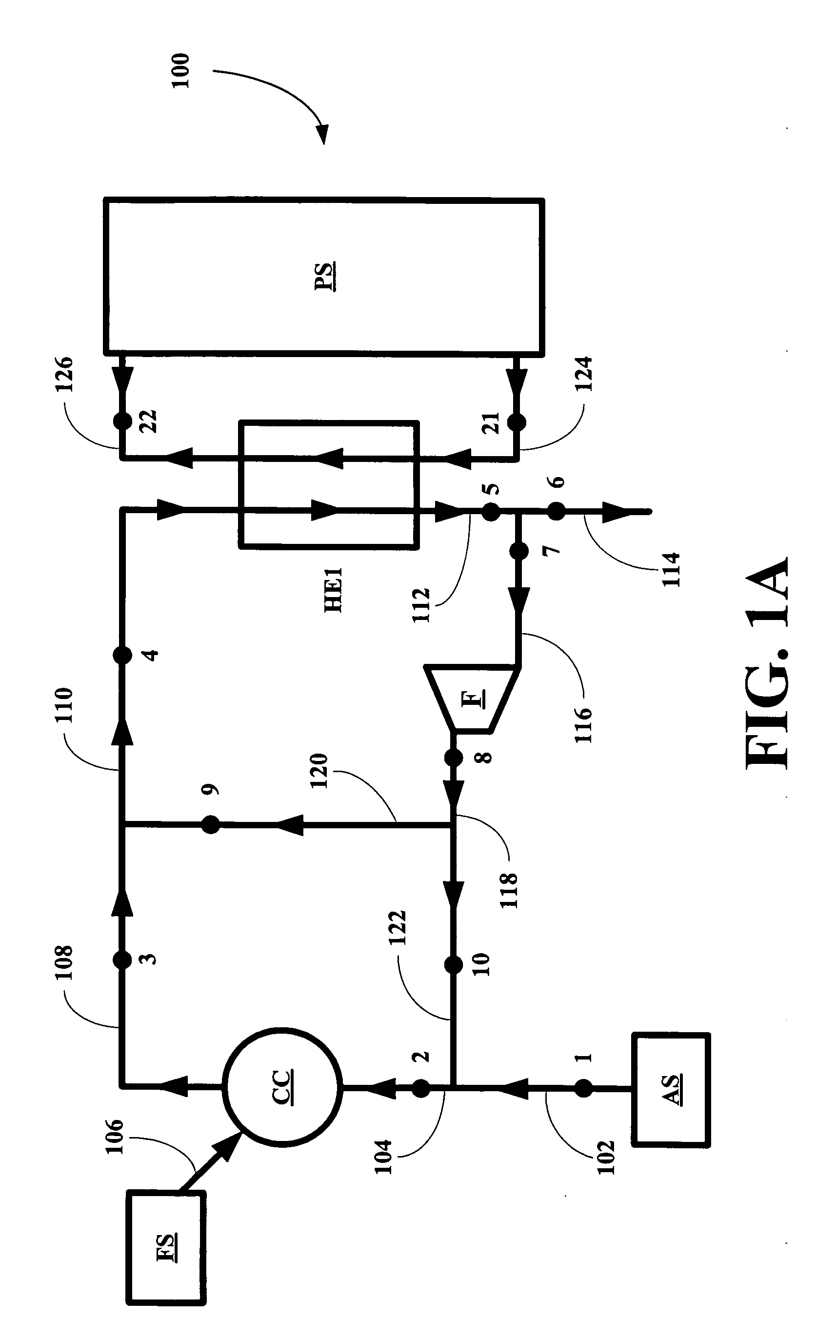
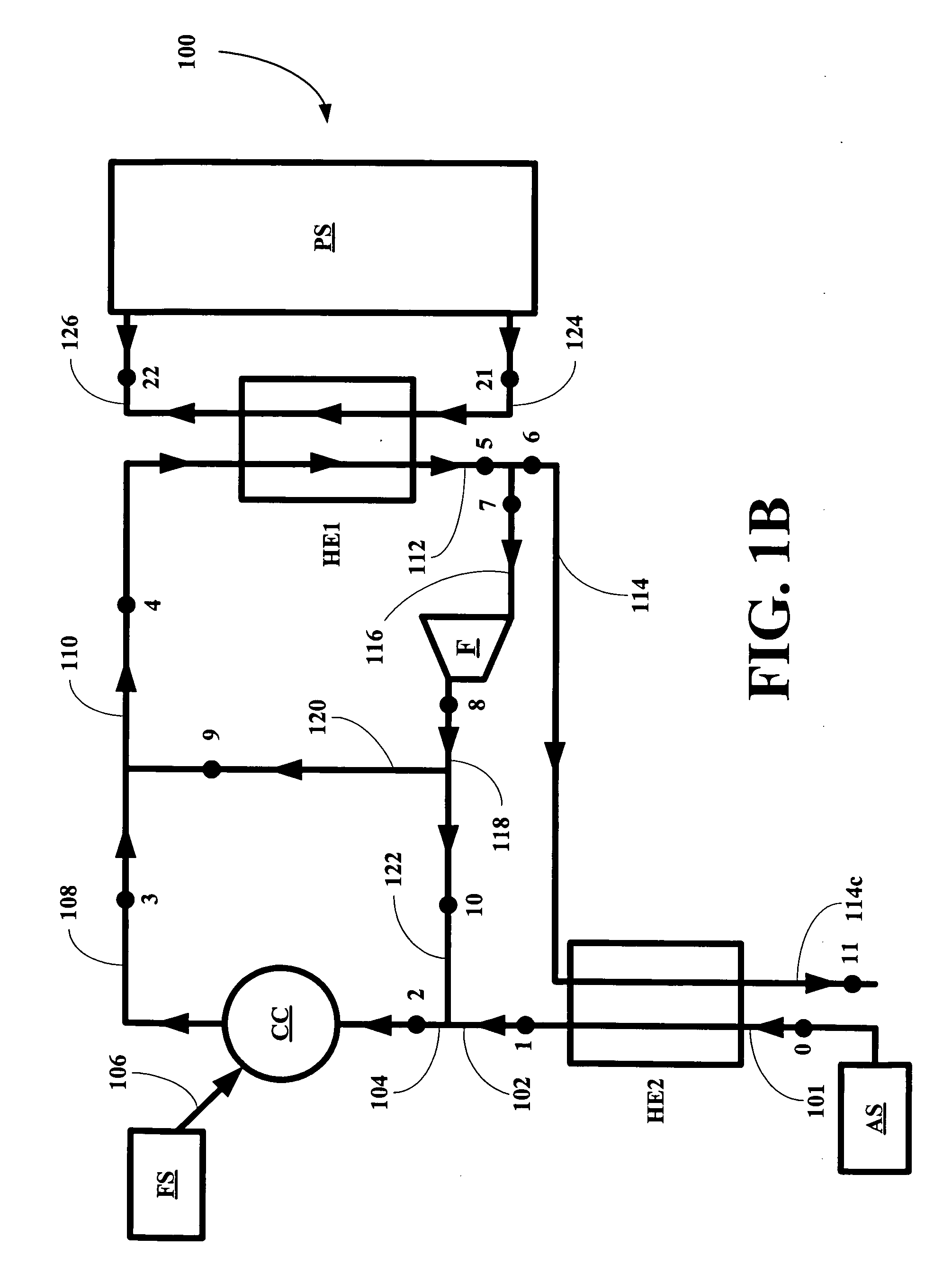
[0024] The inventors have found that a combustion apparatus can be constructed that allows combustion of fuels with a minimum excess of air, in order to attain a high efficiency, and at the same time allows effective control of temperatures in combustion chambers and temperatures of produced flue gases. The design allows direct utilization of heat in type heat exchangers used in heat recovery steam generator (HRSG) or a heat recovery vapor generator (HRVG). The designs of this invention are simpler and more cost effective than prior art combustion apparatuses. In one embodiment of the combustion method and corresponding apparatus of this invention, the temperature of the moderate temperature flue gas stream supplied to the heat exchangers of generators can range between about 1000° F. and about 250° F. In another embodiment, the temperature ranges between about 800° F. and about 250° F. In another embodiment, the temperature ranges between about 600° F. and about 250° F. The method ...


PUM


Abstract

An improved combustion method and corresponding apparatus is disclosed, where the method includes oxidizing a fuel in a combustion chamber with an oxidizing stream including an air stream and a first recycled flue gas stream and mixing a produced hot flue gas stream with a second recycled flue gas stream to form reduced temperature flue gas stream which can be used directly in a power generator or to heat a reactor. The method and apparatus allow flow rates of the streams to be adjusted so that temperatures in the combustion chamber and in the heat transfer unit or units of the power generator or reactor can be kept below temperature that would thermally damage the combustion chamber, heat transfer unit or units or the reactors.

Description

BACKGROUND OF THE INVENTION [0001] 1. Field of the Invention [0002] The present invention relates to the field of combusting fuels with the aim of supplying heat to thermal power plants and / or for other purposes. [0003] More particularly, the present invention relates to a combustion apparatus including a combustion chamber, a source of air and a flue gas recirculation system and methods for making and using same. [0004] 2. Description of the Related Art [0005] In the process of the combustion of fuels, a minimum quantity of air, that is theoretically necessary for complete combustion of the fuel, is such that all oxygen contained in the air supplied to the combustion is completely consumed or used. Such a process is referred as a stoichiometric process, and corresponds to the highest temperature in the combustion zone given a combustion process that uses air as the oxidant. [0006] However, in actual practice, all current industrially used combustion systems operate with some excess...

Claims


Application Information

Patent Timeline
IPC IPC(8): F23M3/00
CPCF22B35/002F23C9/08F23C2202/30F23L15/04Y02E20/34
Inventor KALINA, ALEXANDER I.
Owner KALINA POWER LTD
Why Eureka
Try Eureka