Cyclone furnace for oxygen fired boilers with flue gas recirculation

Inactive Publication Date: 2006-09-14
THE BABCOCK & WILCOX CO
View PDF3 Cites 11 Cited by
  • Summary
  • Abstract
  • Description
  • Claims
  • Application Information

AI Technical Summary

Benefits of technology

[0004] It is an object of the present invention to provide a cyclone furnace method and appa

Problems solved by technology

However, along with the high concentration of carbon dioxide in the recirculated flue gas is also a high concentration of moistu

Method used


Image

  • Cyclone furnace for oxygen fired boilers with flue gas recirculation
  • Cyclone furnace for oxygen fired boilers with flue gas recirculation

Examples


Example

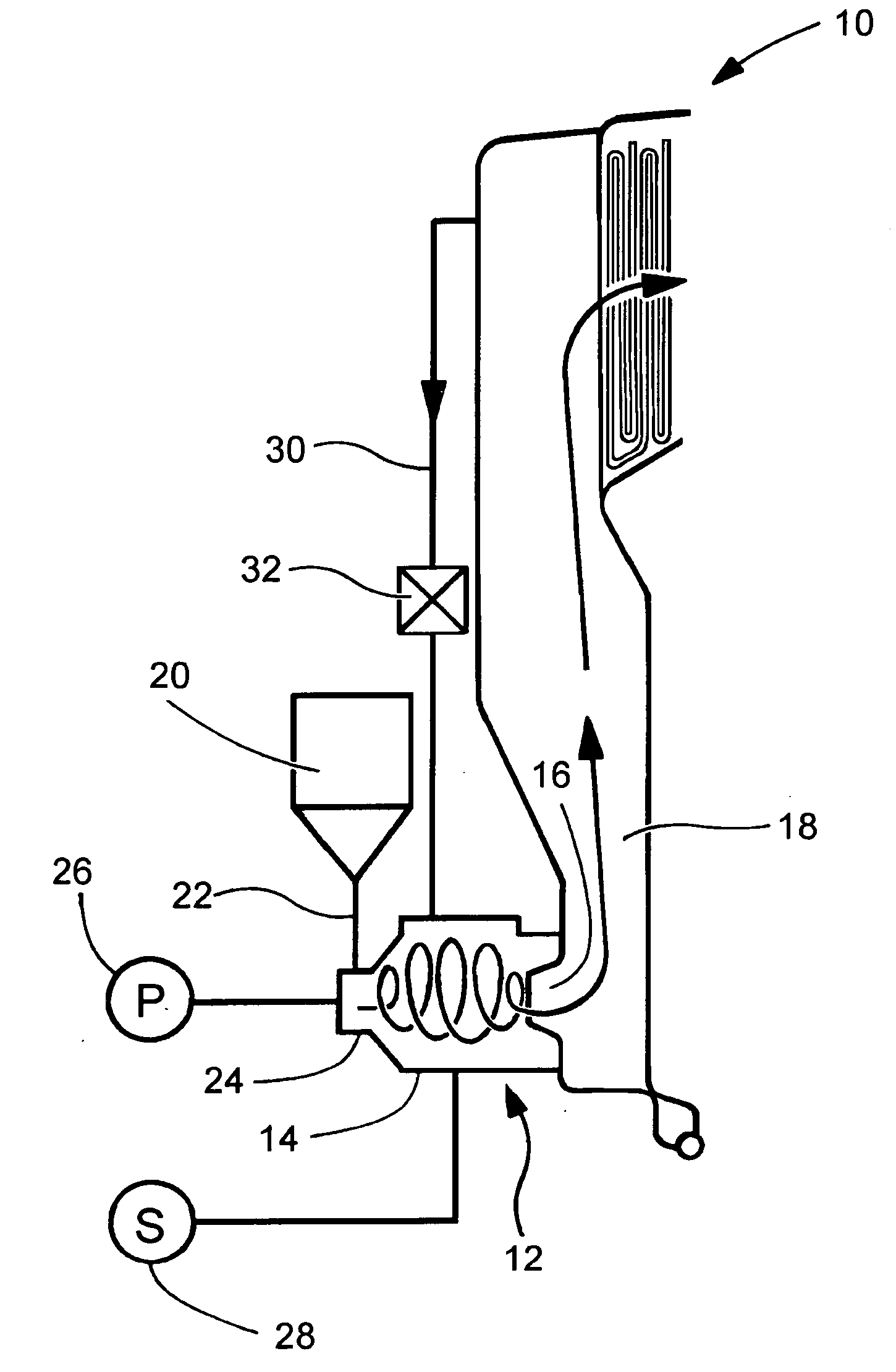
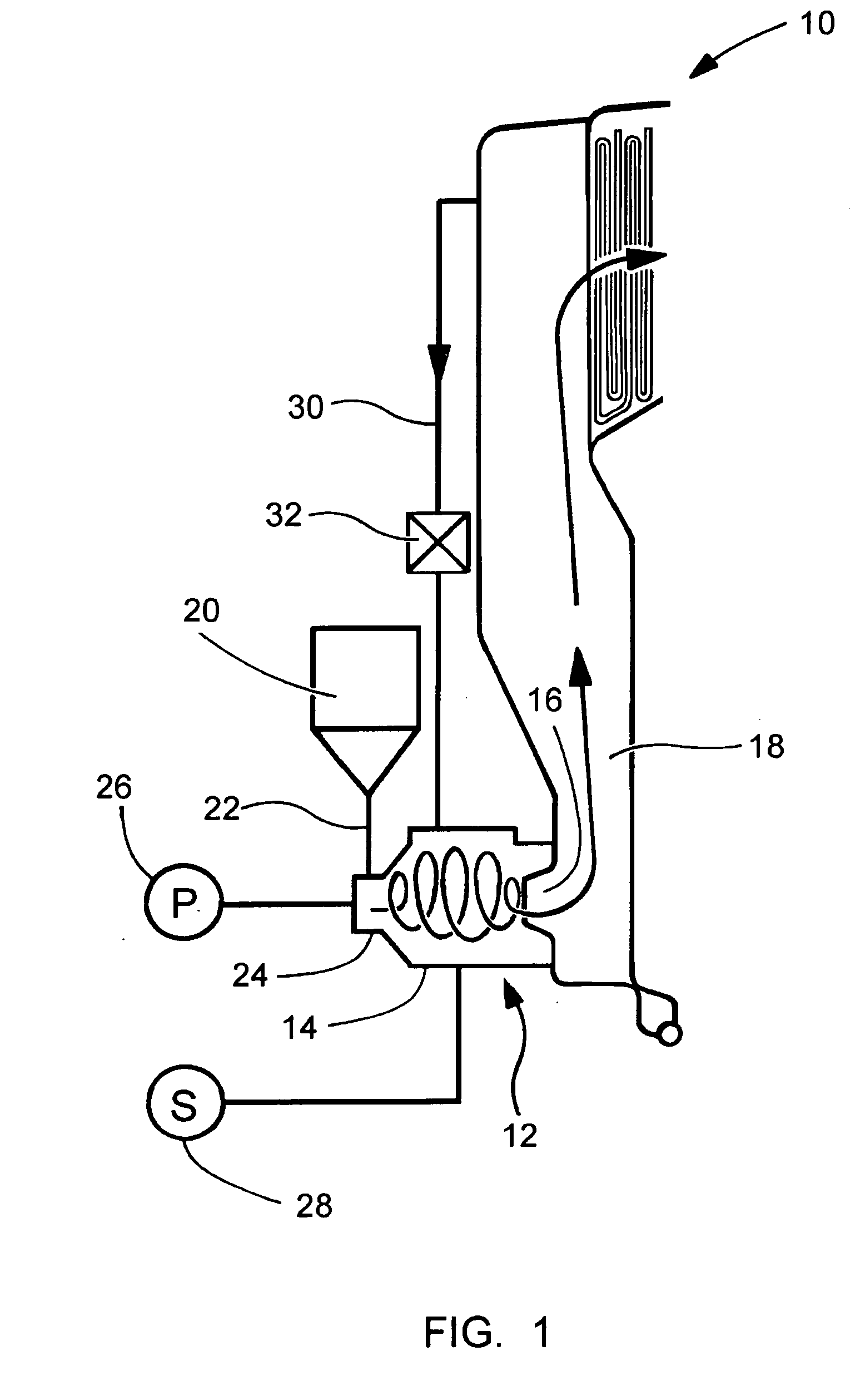
[0012] Referring now to the drawing, FIG. 1 shows a cyclone furnace generally designated 10 having a cyclone burner generally designated 12 with a generally cylindrical cyclone barrel 14 having an outlet or re-entrant throat 16 for discharging combustion products that have been produced in the cyclone furnace as will be explained later in this disclosure. The throat 16 is connected to the lower end of a main furnace 18 with the upwardly directed arrows identify the combustion products which include flue gases that are rich in carbon dioxide.

[0013] Heat from these hot combustion products are taken away preferably by tubes containing water and / or steam in the environment of a boiler where the heat is used for other purposes.

[0014] Crushed rather than pulverized coal is stored in a coal bunker 20 and, using known equipment, is supplied along a fuel supply line 22 to a crushed coal inlet at the top of a radial burner 24. Primary and tertiary flue gas are supplied to burner 24 by suppl...


PUM


Abstract

A cyclone furnace and method uses a cyclone burner having a cyclone barrel with a re-entrant throat connected to a main furnace for passing combustion products including flue gas that is rich in carbon dioxide. Crushed coal and oxygen are supplied the cyclone burner and at least some of the flue gas from the main furnace is recirculated to the cyclone barrel.

Description

FIELD AND BACKGROUND OF INVENTION [0001] The present invention relates generally to the field of furnaces, and in particular to a new and useful cyclone furnace which produces reduced emissions of NOx. [0002] Cyclone furnaces have been in use since the early 1950's as an efficient method for combusting coal. They also allow for a smaller boiler because up to 90% of the ash is tapped out of the furnace bottom permitting a smaller convection pass without slagging on the heat transfer surface. However, with the more stringent NOx emissions in today's environment, cyclone furnaces are no longer a desirable method of coal combustion because of their heavy NOx production. [0003] More information about the construction and operation of cyclone furnaces can be found in the publication STEAM—ITS GENERATION AND USE, 40TH EDITION, published by Babock & Wilcox, a McDermott Company, at Chapter 14. SUMMARY OF INVENTION [0004] It is an object of the present invention to provide a cyclone furnace m...

Claims


Application Information

Patent Timeline
IPC IPC(8): F23D1/00
CPCF23C5/12F23C6/04F23C9/003
Inventor DEVAULT, DOUGLAS J.MCDONALD, DENNIS K.
Owner THE BABCOCK & WILCOX CO
Why Eureka
Try Eureka