
Magnetic sensor for electromagnetic measurement

a magnetic sensor and electromagnetic technology, applied in wave based measurement systems, instruments, reradiation, etc., can solve the problems of low noise amplifier at low frequency and low noise that is hardly achievable, and achieve the effect of minimizing the effect of a current noise source, increasing the self-resonance frequency of the sensing coil, and reducing the noise of the current sour

Active Publication Date: 2006-09-14
BAKER HUGHES INC
View PDF14 Cites 52 Cited by
  • Summary
  • Abstract
  • Description
  • Claims
  • Application Information

AI Technical Summary

Benefits of technology

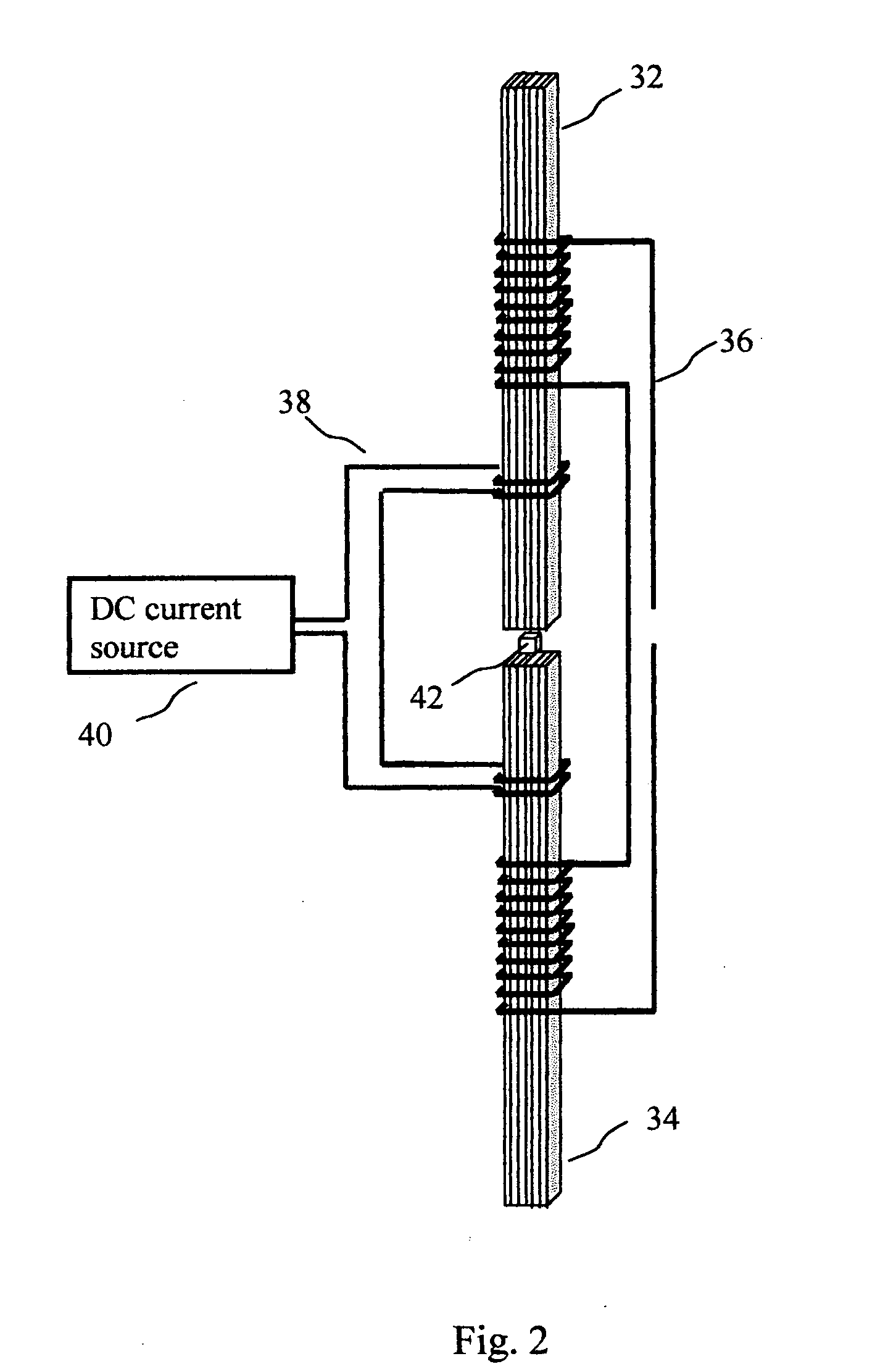
The present invention is an instrument for measuring the electromagnetic properties of geological formations. It includes a transmitter to generate a time-varying electric current in the formations and a magnetic sensing assembly. The sensing assembly has a magnetic core with high magnetic permeability and a sensing coil wound on the magnetic core to produce voltage signals proportional to the time rate of change of the magnetic field generated by the current in the formations. The magnetic sensor is a chip-scale atom-optical magnetometer or a miniature fluxgate sensor. The dimensions of the magnetic core are chosen to minimize noise. The assembly also includes an acquisition means to process the voltage signals from the magnetic sensor and the sensing coil to provide a low noise output with flat transfer function over a wide frequency range. The acquisition means can measure the voltage signals in a selected digitizing time window and cumulatively sum over a number of cycles to average out signals incoherent with the magnetic field generated by the current in the formations. The magnetic sensing assembly can also have an adjustment element to control and cancel out a background magnetic field. The sensing coil can have multiple sections, each section connected to a low noise operational amplifier to minimize the effects of current noise and increase the self-resonance frequency of the coil. The sensing coil can also be connected to multiple low noise FET operational amplifiers in parallel to minimize the effects of voltage noise.

Problems solved by technology

It also requires very low noise amplifier at low frequency where low noise is hardly to achieve due to 1 / f-type noise of an operational amplifier.

Method used


Image

  • Magnetic sensor for electromagnetic measurement
  • Magnetic sensor for electromagnetic measurement
  • Magnetic sensor for electromagnetic measurement

Examples


Embodiment Construction

[0021] In most general terms, the invention provides a high sensitivity magnetic sensor facilitating measurement in a wide frequency range of time-varying magnetic fields generated by electric current in electromagnetically energized geological formations.

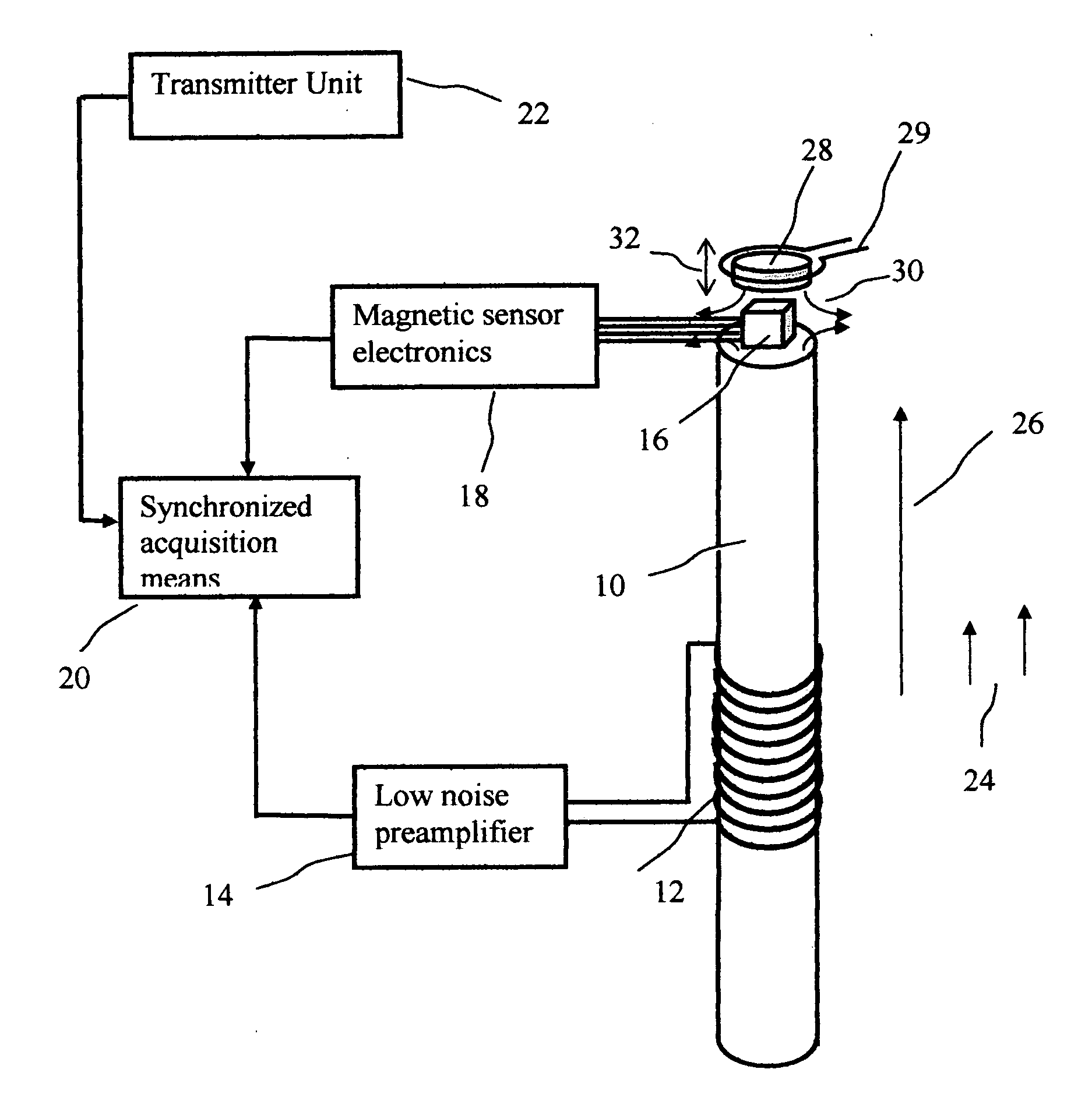
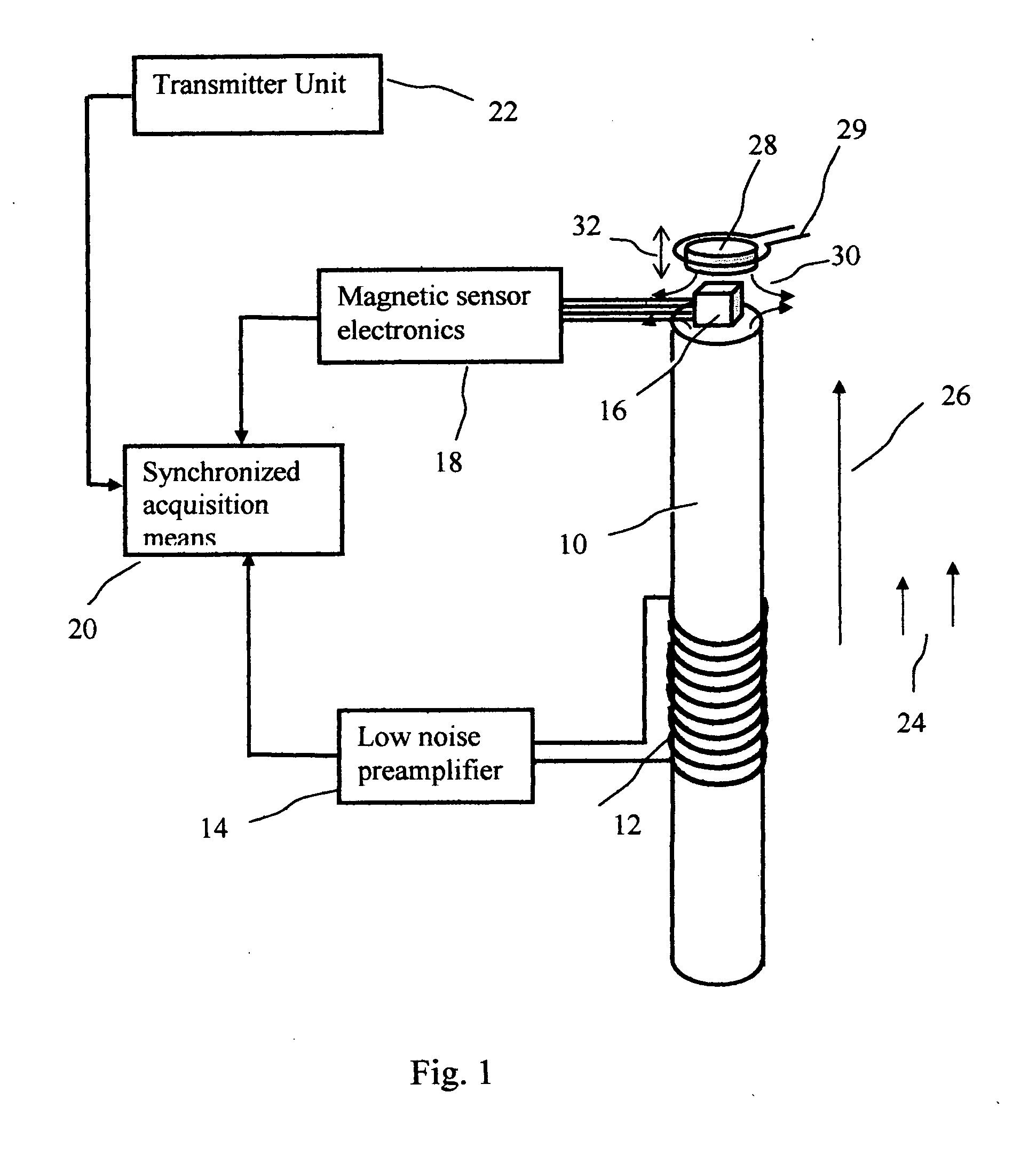
[0022]FIG. 1 represents a simplified layout of a preferred embodiment of the magnetic sensor assembly according to the present invention. The assembly comprises a high permeability magnetic core 10, a coil 12 wound on the core and a miniature low magnetic noise magnetic sensor 14 placed near an edge of the magnetic core 10. The magnetic core has a large length-to-diameter ratio and a direction of elongation preferably set to be collinear with a component of the time-varying magnetic field 24 to be measured. A recently developed chip-scale atomic magnetometer (CSAM) described in P. D. D. Schwindt, et. al., “Chip-scale atomic magnetometer,”Appl. Phys. Lett. 85, 6409, 2004 or its modifications can be used as the low noise magnetic se...


PUM


Abstract

A magnetic sensing assembly for measuring magnetic field produced by a time varying electric current generated in geological formations is disclosed. The assembly comprises a soft magnetic core, a sensing coil wound on the core, and at least one miniature low noise magnetic field sensor disposed near an edge of the magnetic core. Due to strong magnetic flux concentration effect of the magnetic core the sensor facilitates very low noise magnetic measurements at a low rate of change of the magnetic field, while the sensing coil offers high sensitivity and low noise measurement at higher rates. The magnetic sensing assembly preferably comprises an earth field cancellation element. The assembly also includes an acquisition means synchronized with an electromagnetic transmitter to receive and process signals from sensing coil and from magnetic field sensor.

Description

CROSS-REFERENCE TO RELATED APPLICATIONS [0001] Not applicable. STATEMENT REGARDING FEDERALLY SPONSORED RESEACH OR DEVELOPMENT [0002] Not applicable. BACKGROUND OF THE INVENTION [0003] 1. Field of the Invention [0004] The invention relates generally to the field of electromagnetic methods in geological formation exploration and evaluation. More particularly, the invention relates to a high sensitive magnetic sensing assembly for measuring magnetic field produced by a current flowing in the earth formations energized by an electromagnetic energy source. The invention also relates to the application of transient electromagnetic method, magnetometric resistivity, deep induction well logging and induction cross-hole imaging. [0005] 2. Background Art [0006] In electromagnetic geophysical exploration and formation evaluation, electromagnetic signals are received and processed to provide information on conductivity distribution of the earth formations. The receiving sensors used for these p...

Claims


Application Information

Patent Timeline
Patent Type & Authority Applications(United States)
IPC IPC(8): G01R33/04
CPCG01V3/28
Inventor REIDERMAN, ARCADY
Owner BAKER HUGHES INC
Learn More