Digital switching amplifier

a switching amplifier and digital technology, applied in the direction of amplifiers with negative feedback circuit arrangements, amplifiers with semiconductor devices/discharge tubes, amplifier modifications to reduce noise influence, etc., can solve problems that need to be solved, and achieve the effect of increasing s/n ratio, reducing current consumption, and further reducing quantizing nois

Active Publication Date: 2006-09-14
ASAHI KASEI ELECTRONICS CO LTD
View PDF4 Cites 38 Cited by
  • Summary
  • Abstract
  • Description
  • Claims
  • Application Information

AI Technical Summary

Benefits of technology

[0033] That is to say, the present invention produces an effect by which quantizing noise can be further reduced in comparison with the first example of related art described above, enabling further increasing an S/N ratio, and further decreasing a current consumption.
[0034] According to the present i

Problems solved by technology

In such a field, however, there have been several problems to

Method used


Image

  • Digital switching amplifier
  • Digital switching amplifier
  • Digital switching amplifier

Examples


first embodiment

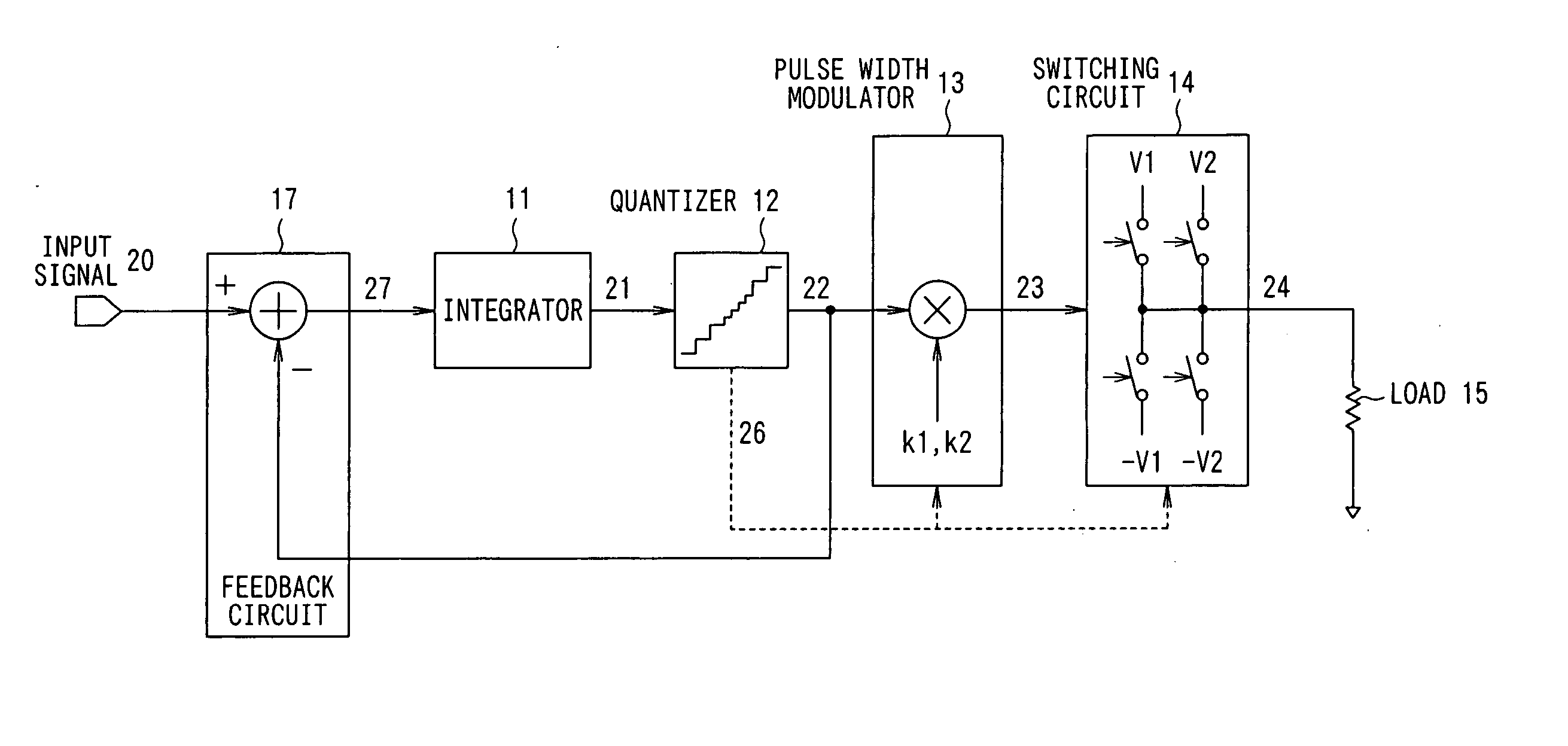
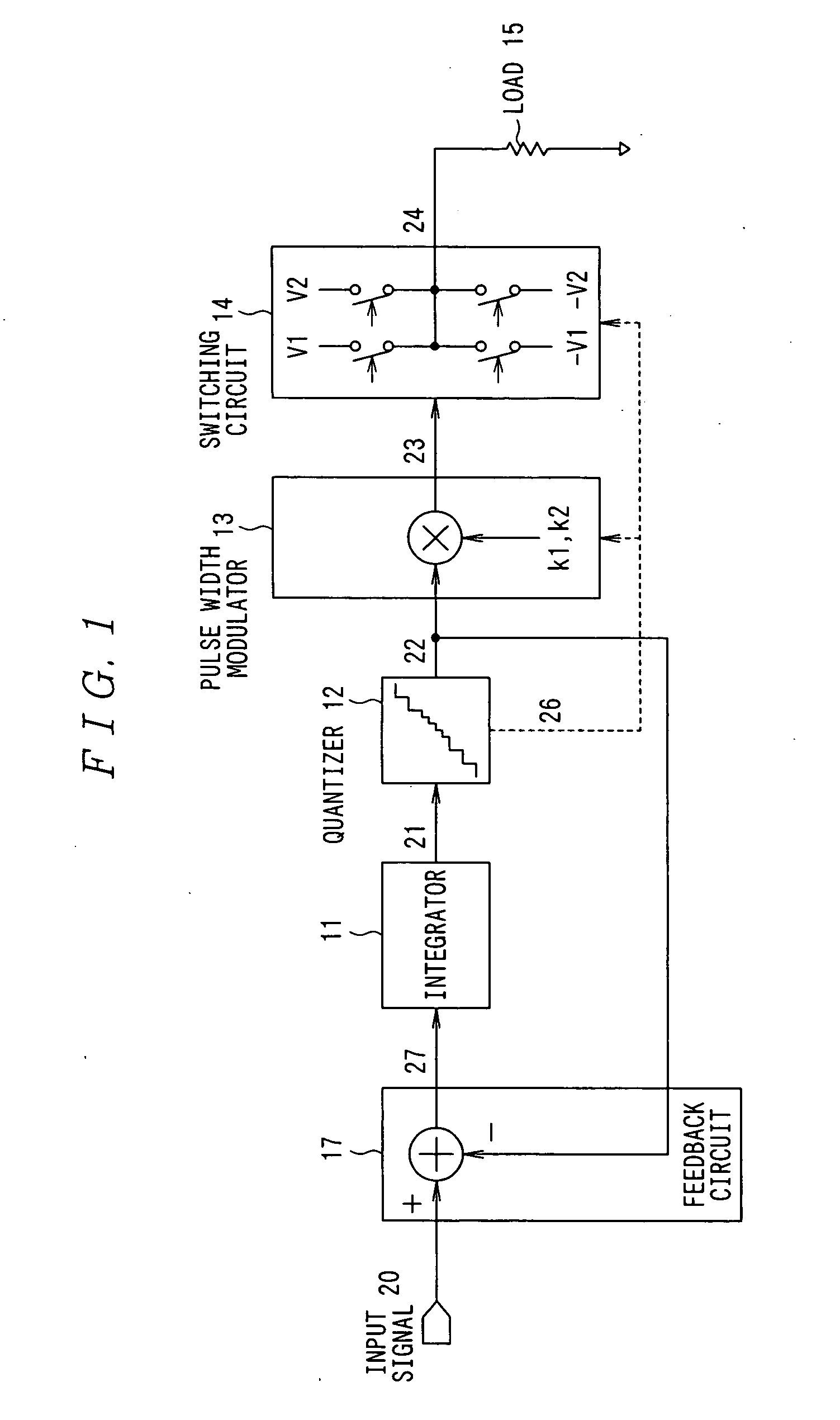
[0051] The configuration of a first embodiment of a digital switching amplifier according to the present invention is described with reference to FIG. 1.

[0052] As shown in FIG. 1, the digital switching amplifier in the first embodiment includes an integrator 11, quantizer 12, pulse width modulator 13, switching circuit 14, and feedback circuit 17 for negatively feeding back the output of the quantizer 12 to the input of the integrator 11. The output of the switching circuit 14 drives a load 15 such as a loud speaker and the like.

[0053] The integrator 11 is a circuit to integrate an input signal 20 as an analog or digital signal. The output 21 of the integrator 11 is supplied to the quantizer 12.

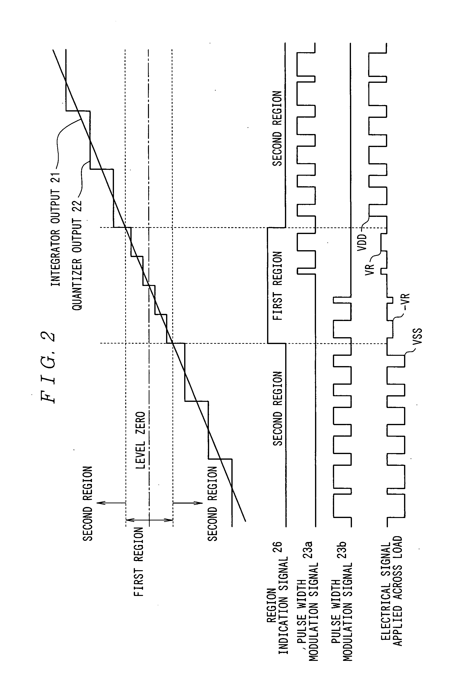
[0054] The quantizer 12 is a circuit to quantize the output 21 of the integrator 11 with predetermined resolutions different for each of signal regions (signal level region) (refer to FIG. 2). The output 22 of the quantizer 12 is fed into the pulse width modulator 13 and fed back to the in...

second embodiment

[0098] The configuration of a second embodiment of the digital switching amplifier according to the present invention is described with reference to FIG. 9.

[0099] As shown in FIG. 9, the digital switching amplifier according to the second embodiment includes an integrator 11, quantizer 12, pulse width modulator 13, switching circuits 14a and 14b, and feedback circuit 17 for negatively feeding back the output of the quantizer 12 to the input of the integrator 11. Differential output of a pair of the switching circuits 14a and 14b drives both terminals of the load 15 such as a loudspeaker and the like.

[0100] The second embodiment is the same in basic configuration as the first embodiment shown in FIG. 1, so that the same components are given the same reference characters to omit describing the configuration, and points different in configuration are mainly described.

[0101] That is to say, the second embodiment includes a pair of switching circuits 14a and 14b instead of the switchi...

third embodiment

[0119] The configuration of a third embodiment of the digital switching amplifier according to the present invention is described with reference to FIG. 11.

[0120] As shown in FIG. 11, in the third embodiment, the digital switching amplifier includes an integrator 11, quantizer 12, pulse width modulator 13, switching circuit 14, and feedback circuit 17a for negatively feeding back the output of the switching circuit 14 to the input of the integrator 11. The output of the switching circuit 14 drives the load 15 such as a loudspeaker and the like.

[0121] The third embodiment is the same in basic configuration as the first embodiment shown in FIG. 1, so that the same components are given the same reference characters to omit describing the configuration, and points different in configuration are mainly described.

[0122] That is to say, in the third embodiment, the feedback circuit 17 shown in FIG. 1 is replaced by a feedback circuit 17a as depicted in FIG. 11. The feedback circuit 17a ...


PUM


Abstract

There is provided a digital switching amplifier capable of enhancing an S/N ratio at the time of a small signal output and reducing current consumption and electromagnetic interference (EMI). The digital switching amplifier according to the present invention is provided with an integrator 11 for integrating an input signal, quantizer 12 for quantizing the output signal of the integrator 11 with resolutions different for each of the predetermined signal regions, pulse width modulator 13 for performing pulse width modulation for each of signals quantized with different resolutions by the quantizer 12 using different proportionality coefficients, switching circuit 14 for providing the load 15 with electrical signals different in value for each of pulse-width modulated signals with different proportionality coefficients by the pulse width modulator 13 in response to the pulse-width modulated signal, and feedback circuit 17 for negatively feeding back the output of the quantizer 12 to the input of the integrator 11.

Description

BACKGROUND OF THE INVENTION [0001] 1. Field of the Invention [0002] The present invention relates to a digital switching amplifier for outputting digital switching signals to drive a resistive, capacitive, or inductive load such as a loudspeaker, headphone, piezoelectric element, heating element, electric motor, or for outputting electrical signals such as voltage, current, or charge. [0003] 2. Description of the Related Art [0004] In an audio field, for instance, a digital switching amplifier (or D class amplifier) has been known as an amplifier for driving a low resistive load such as loudspeaker, headphone, and the like to produce an analog audio signal. The amplifier is very useful as a component used in a miniaturized set because it produces a large amplitude output and can be easily integrated into LSI due to its lower heating characteristic resulting from small voltage drop in an amplifier. [0005] In such a field, however, there have been several problems to be solved before ...

Claims


Application Information

Patent Timeline
IPC IPC(8): H03F1/36
CPCH03F1/26H03F1/34H03F3/217H03F2200/331
Inventor YAMAMURA, KENIKEHARA, AKIHIROHYODO, NAOKO
Owner ASAHI KASEI ELECTRONICS CO LTD
Why Eureka
Try Eureka