Optical element and exposure apparatus

a technology applied in the field of optical elements and exposure apparatuses, can solve the problems of failure to obtain a desired optical performance, and achieve the effect of preventing the deterioration of the sealing member

Inactive Publication Date: 2006-09-14
NIKON CORP
View PDF85 Cites 51 Cited by
  • Summary
  • Abstract
  • Description
  • Claims
  • Application Information

AI Technical Summary

Benefits of technology

[0011] According to the optical element of the first aspect, the first anti-dissolution member is formed on the surface (a tip surface) of the optical element. Therefore, it is possible to prevent dissolution of the optical element and thereby to maintain an optical performance of the projection optical system.
[0122] According to the exposure apparatus of any one of the sixtieth to sixty-second aspects, it is possible to prevent irradiation of the exposure light beam and reflected light of the exposure light beam from a wafer onto the sealing member formed in the peripheral portion of the side surface (the tapered surface) of the transmissive optical element on the substrate's side of the projection optical system by use of the light-shielding film. In this way, it is possible to prevent deterioration of the sealing member.

Problems solved by technology

Accordingly, there is a risk that a tip portion of the projection optical system contacting the liquid may be corroded by the liquid, thereby leading to a failure to obtain a desired optical performance.
Since the projection optical system contacts the liquid, there is a risk that the tip portion of the projection optical system contacting the liquid may be corroded by the liquid, thereby leading to a failure to obtain a desired optical performance.

Method used


Image

  • Optical element and exposure apparatus
  • Optical element and exposure apparatus
  • Optical element and exposure apparatus

Examples


embodiment 1

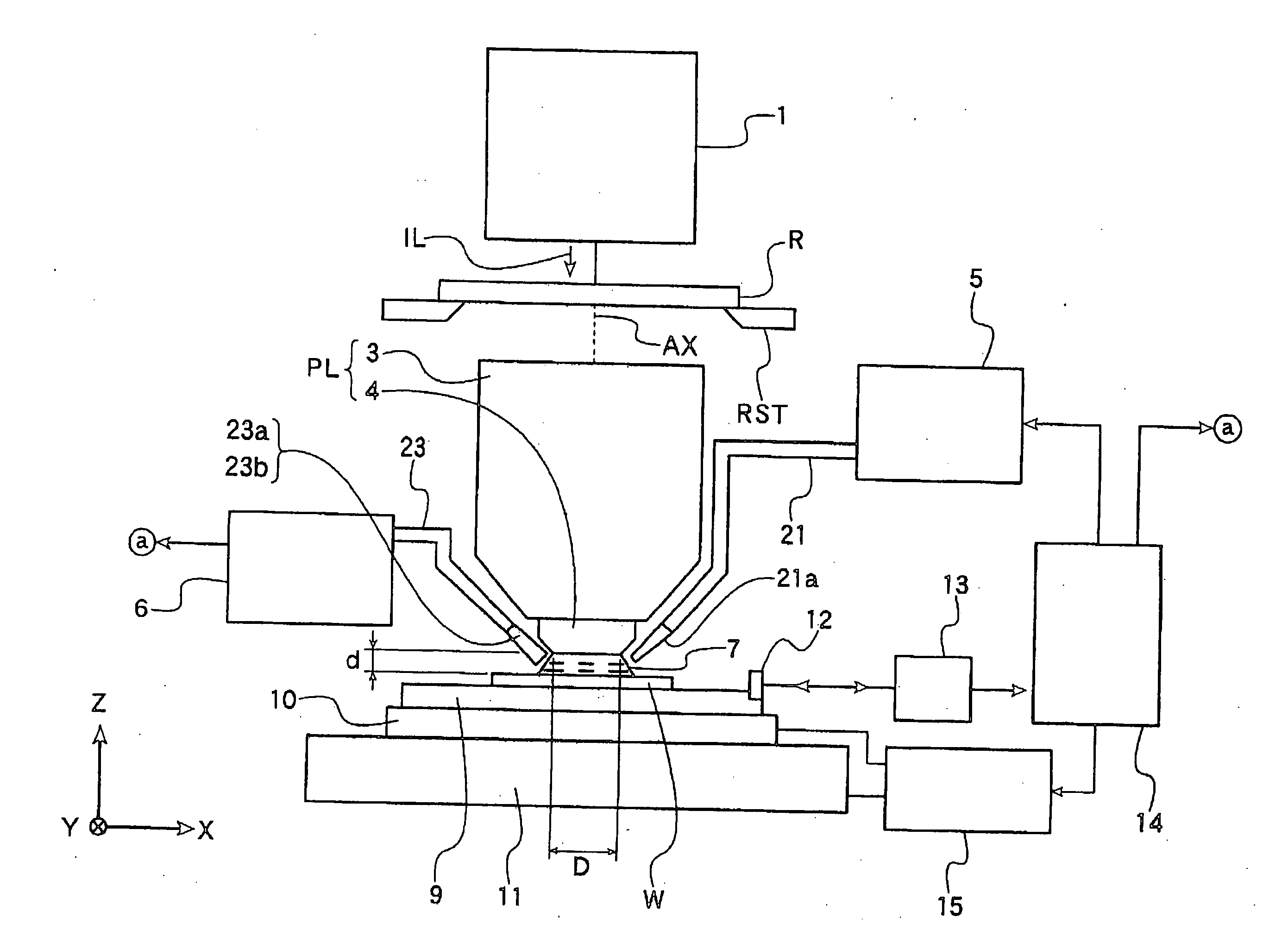
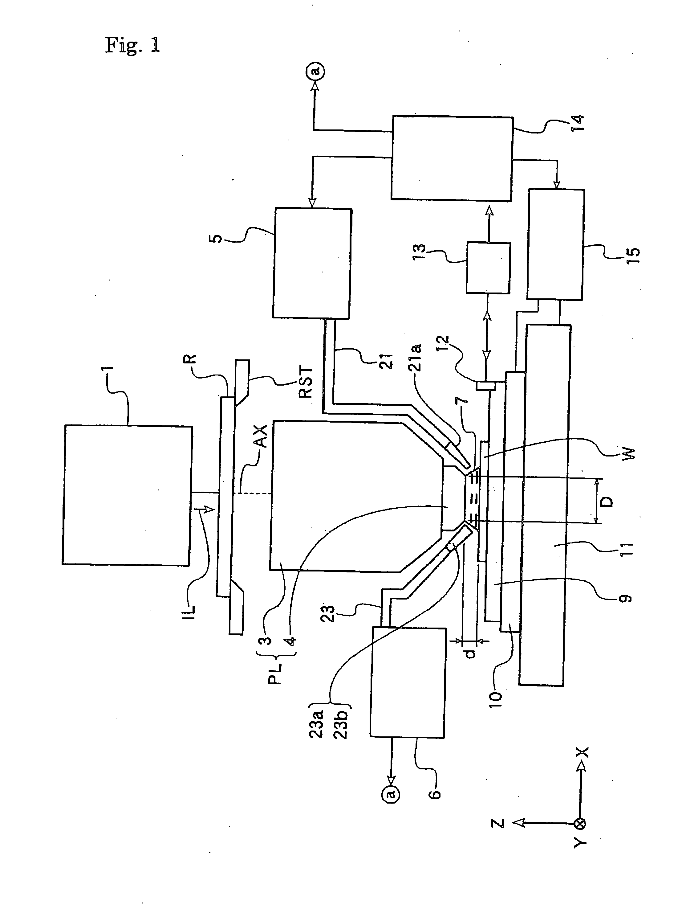
[0181] A projection exposure apparatus according to Embodiment 1 of this invention will now be described with reference to the accompanying drawings. FIG. 1 is a view showing a schematic configuration of a projection exposure apparatus applying the step and repeat method according to Embodiment 1. It is to be noted that an XYZ orthogonal coordinate system as illustrated in FIG. 1 will be set up in the following explanation, and positional relations of respective members will be described with reference to this XYZ orthogonal coordinate system. In terms of the XYZ orthogonal coordinate system, an X axis and a Y axis are set parallel to a wafer W while a Z axis is set in the orthogonal direction to the wafer W. In terms of the XYZ orthogonal coordinate system in the figure, an XY plane is actually set to a parallel plane to a horizontal plane while the Z axis is set in the vertical direction.

[0182] As shown in FIG. 1, the projection exposure apparatus according to this embodiment is ...

embodiment 2

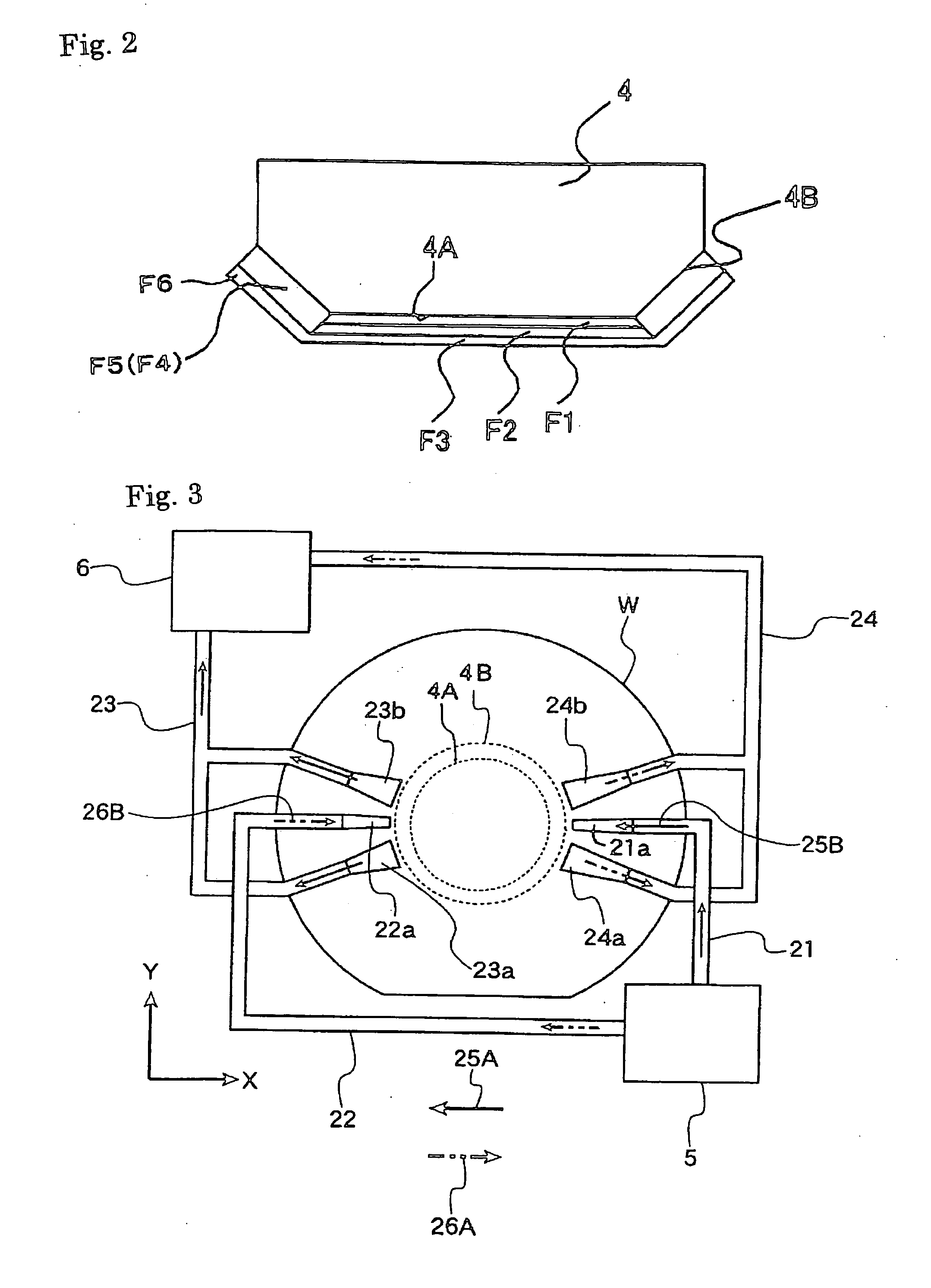
[0229] A projection exposure apparatus is configured as similar to that of Embodiment 1 except that a magnesium fluoride (MgF2) film is formed at the tip portion 4A of the optical element 4, or in other words, at the portion contacting the liquid 7, as the single-layered anti-dissolution film by use of the vacuum vapor deposition method.

[0230] According to the projection exposure apparatus of this Embodiment 2, the single-layered anti-dissolution film is formed on the surface of the optical element, and it is thereby possible to prevent dissolution of the optical element. Further, it is possible to reduce the interface as compared to the multilayer film. Therefore, it is possible to minimize an adverse effect attributable to a chemical reaction which is apt to occur when the liquid infiltrates into the interface of the protective layer serving as the anti-dissolution film. Moreover, it is easier to form the film as compared to formation of the anti-dissolution film including the mu...

embodiment 3

[0232] A projection exposure apparatus is configured as similar to Embodiment 1 except that the transmissive optical element 4 is modified as shown in FIG. 6 and as described below.

[0233] (i) The magnesium fluoride (MgF2) film F1 is formed at the tip portion 4A of the optical element 4 on the wafer W side, or in other words, at the portion where the exposure light beam passes through, constituted of the single-layered anti-dissolution film by use of the vacuum vapor deposition method.

[0234] (ii) The tantalum (Ta) film serving as the adhesion reinforcing film F4 is formed on the tapered surface 4B of the transmissive optical element 4, or in other words, at the portion where the exposure light beam does not pass through by use of the sputtering method. The adhesion reinforcing film F4 is used for improving adhesion between the tapered surface 4B of the transmissive optical element 4 and the metal anti-dissolution film (the anti-dissolution film) F5 to be described later.

[0235] (ii...


PUM


Abstract

An optical element is used for an exposure apparatus which is configured to illuminate a mask with an exposure light beam for transferring a pattern on the mask onto a substrate through a projection optical system and to interpose a given liquid in a space between a surface of the substrate and the projection optical system. The optical element includes a first anti-dissolution member provided on a surface of a transmissive optical element on the substrate's side of the projection optical system.

Description

[0001] This is a Division of application Ser. No. 10 / 569,207, which is the U.S. National Stage of PCT / JP2004 / 012296 filed Aug. 26, 2004. The disclosures of the prior applications are hereby incorporated by reference herein in their entireties.TECHNICAL FIELD [0002] The present invention relates to an optical element used in a projection exposure apparatus adopting the liquid immersion method, which is applied to the lithography step for transferring a mask pattern onto a photosensitive substrate to produce devices including, for example, semiconductor elements, image pickup devices (such as CCDs), liquid crystal display elements, and thin film magnetic heads. The present invention also relates to an exposure apparatus applying the optical element. BACKGROUND ART [0003] A projection exposure apparatus configured to transfer a pattern image of a reticle as a mask onto each shot area on a resist-coated wafer (or a glass plate and so forth) serving as a photosensitive substrate through ...

Claims


Application Information

Patent Timeline
Patent Type & Authority Applications(United States)
IPC IPC(8): G03B27/42
CPCG03F7/70341G03F7/70958
Inventor SHIRAI, TAKESHIKOKUBUN, TAKAOISHIZAWA, HITOSHIMURAKAMI, ATSUNOBU
Owner NIKON CORP
Why Eureka
Try Eureka