Multi-terminal type laminated capacitor and manufacturing method thereof

a laminated capacitor, multi-terminal technology, applied in the direction of fixed capacitors, stacked capacitors, fixed capacitor details, etc., can solve the problems of difficult to ensure the adhesion of the terminal electrode with respect to the ceramic porcelain, the fluctuation of the power supply voltage within the allowable value range, and the difficulty of ensuring the adhesion of the terminal electrode with respect to the voltage rang

Active Publication Date: 2006-09-14
TDK CORPARATION
View PDF2 Cites 30 Cited by
  • Summary
  • Abstract
  • Description
  • Claims
  • Application Information

AI Technical Summary

Benefits of technology

[0027] As described above, according to the present invention, even if the number of the layers is reduced or a film thickness of the internal electrode is decreased in order to increase the ESR, it

Problems solved by technology

Therefore, suppressing a fluctuation in power supply voltage within an allowable value range with respect to a sudden change in load current becomes very difficult, and hence a laminated capacitor called a decoupling capacitor is connected with a power supply.
When the film thickness of the extraction electrode is reduced, a sufficient joining structure cannot be provided to the termi

Method used


Image

  • Multi-terminal type laminated capacitor and manufacturing method thereof
  • Multi-terminal type laminated capacitor and manufacturing method thereof
  • Multi-terminal type laminated capacitor and manufacturing method thereof

Examples


Embodiment Construction

[0038]

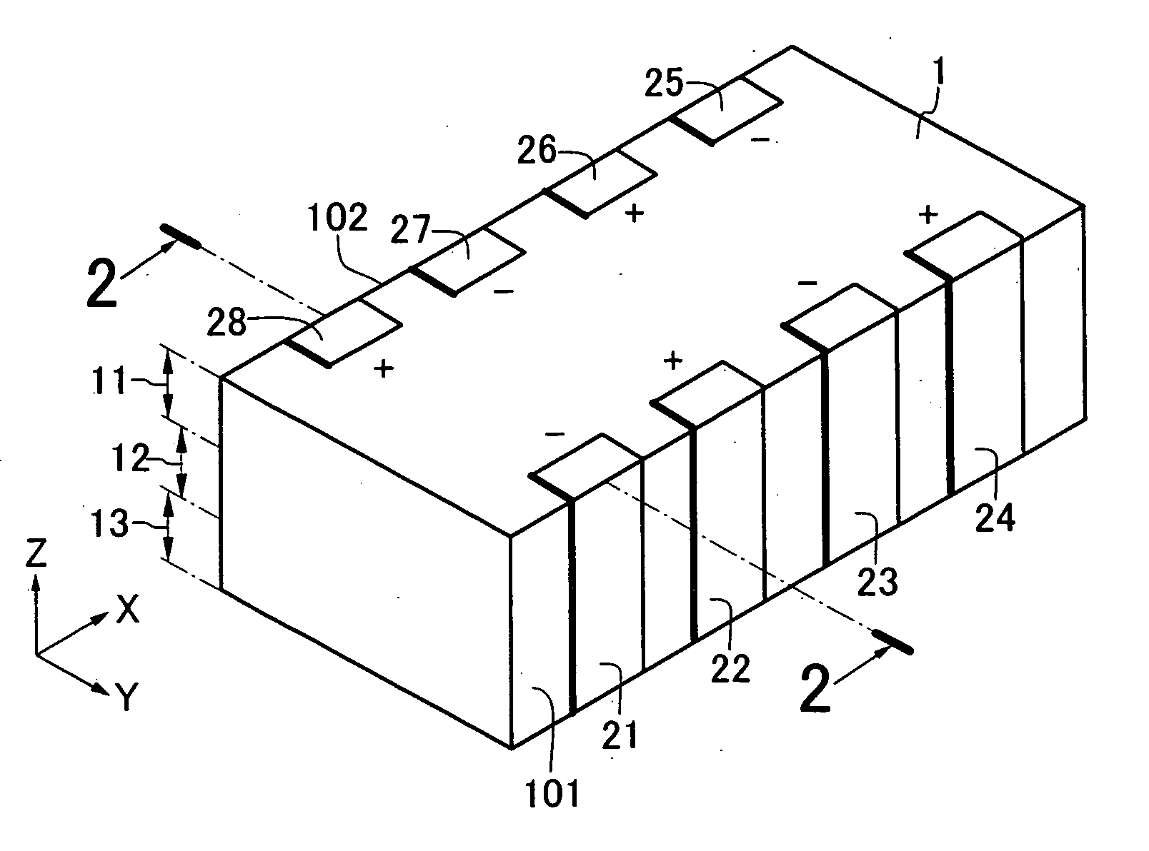
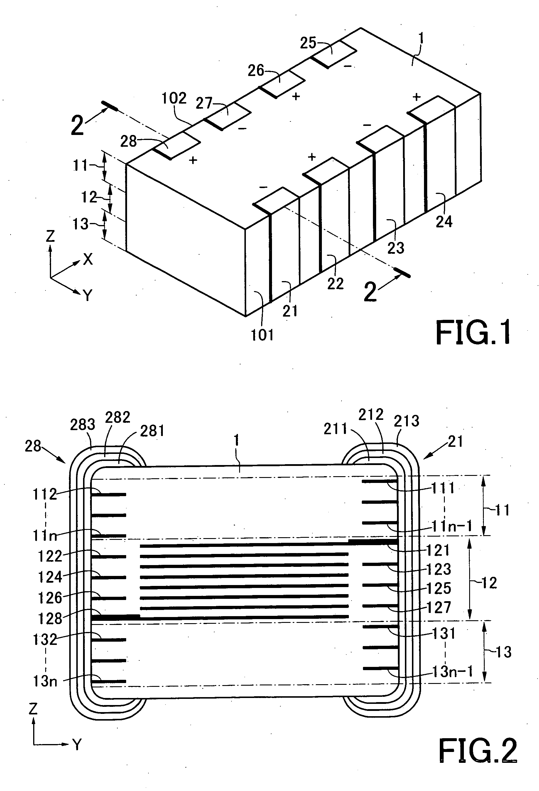
[0039]FIG. 1 is an appearance perspective view showing an embodiment of a multi-terminal type laminated capacitor according to the present invention, and FIG. 2 is a pattern diagram showing a cross section taken along a line 2-2 in FIG. 1. As shown in the drawings, a multi-terminal type laminated capacitor according to the present invention includes a ceramic porcelain 1 and a plurality of electrode layers 121 to 128.

[0040] The ceramic porcelain 1 is formed of a dielectric material or the like mainly containing, e.g., barium titanate. The ceramic porcelain 1 has a substantially rectangular parallelepiped shape having a length direction X, a width direction Y and a thickness direction Z, and terminal electrodes 21 to 24 are provided on one side surface 101 as seen from the width direction Y. These terminal electrodes 21 to 24 are arranged on the side surface 101 at intervals in the length direction X, and the adjacent terminal electrodes have polarities different from each oth...


PUM

PropertyMeasurementUnit
Polarityaaaaaaaaaa

Abstract

Electrode layers 121 to 128 are superimposed in a ceramic porcelain 1 with ceramic layers therebetween. The electrode layers 121 to 128 respectively include internal electrodes A1 to A8 and extraction electrodes B1 to B8. Giving a description on the electrode layer 121, one end of the extraction electrode B1 is connected with the internal electrode A1 in the same layer, and the other end of the same is led onto a side surface of the ceramic porcelain 1. Further, the extraction electrode B1 is formed to be thicker than the internal electrode A1 in the same layer.

Description

BACKGROUND OF THE INVENTION [0001] 1. Field of the Invention [0002] The present invention relates to a multi-terminal type laminated capacitor and a manufacturing method thereof. [0003] 2. Description of the Related Art [0004] In an electric supply source of a central processing unit (CPU) mounted in a digital electronic device, a reduction in voltage advances while a load current is increased. Therefore, suppressing a fluctuation in power supply voltage within an allowable value range with respect to a sudden change in load current becomes very difficult, and hence a laminated capacitor called a decoupling capacitor is connected with a power supply. Further, at the time of a transitional fluctuation in load current, a current is supplied from this laminated capacitor to a CPU, thereby suppressing a fluctuation in power supply voltage. [0005] In recent years, with a further increase in an operating frequency of a CPU, a load current and its speed are increased. Therefore, in the lam...

Claims


Application Information

Patent Timeline
IPC IPC(8): H01G4/06H01G4/12H01G4/232H01G4/30
CPCH01G4/232Y10T29/435H01G4/30A47J37/0694A47J37/0786H05B1/00
Inventor OKUYAMA, HIROSHI
Owner TDK CORPARATION
Why Eureka
Try Eureka