System and method for adaptive switching frequency control

a frequency control and adaptive technology, applied in the field of integrated circuits, can solve the problems of insufficient stability of switch-mode converters, loss often increases with the switching frequency, and the switch-mode converter can consume significant power under standby conditions, so as to improve the stability of the current feedback loop

Active Publication Date: 2006-09-14
ON BRIGHT ELECTRONICS SHANGHAI
View PDF5 Cites 25 Cited by
  • Summary
  • Abstract
  • Description
  • Claims
  • Application Information

AI Technical Summary

Benefits of technology

[0017] Many benefits are achieved by way of the present invention over conventional techniques. For example, some embodiments of the present invention provide an adaptive signal generator. The signal frequency is controlled by at least a control signal generated by a frequency variation generator and another control signal that represents the output loading. For example, the frequency variation generator outputs a randomized signal. In another example, the control signal for output loading includes a feedback voltage. Certain embodiments of the present invention provide an efficient control over switching frequency with low standby power. Some embodiments of the present invention improve stability of the power converter.
[0019] Certain embodiments of the present invention provide a signal generator. The signal slope is compensated for variations in input voltage, and used for slop compensation in a switch-mode power converter. For example, the power converter operates in the current mode. Some embodiments of the present invention sense the input voltage and adjust at least the charging and discharging currents accordingly. Certain embodiments of the present invention provide a ramping signal used for slope compensation. The ratio of slope compensation remains constant with respect to the input voltage. Some embodiments of the present invention improve stability of current feedback loop. Certain embodiments of the present invention use a clock randomizer for frequency modulation.

Problems solved by technology

The switch-mode converters can consume significant power under standby conditions.
These losses often increase with the switching frequency.
But this conventional technique often cannot provide sufficient stability to the switch-mode converters.

Method used


Image

  • System and method for adaptive switching frequency control
  • System and method for adaptive switching frequency control
  • System and method for adaptive switching frequency control

Examples


Embodiment Construction

[0030] The present invention is directed to integrated circuits. More particularly, the invention provides a system and method for frequency control. Merely by way of example, the invention has been applied to a power converter. But it would be recognized that the invention has a much broader range of applicability.

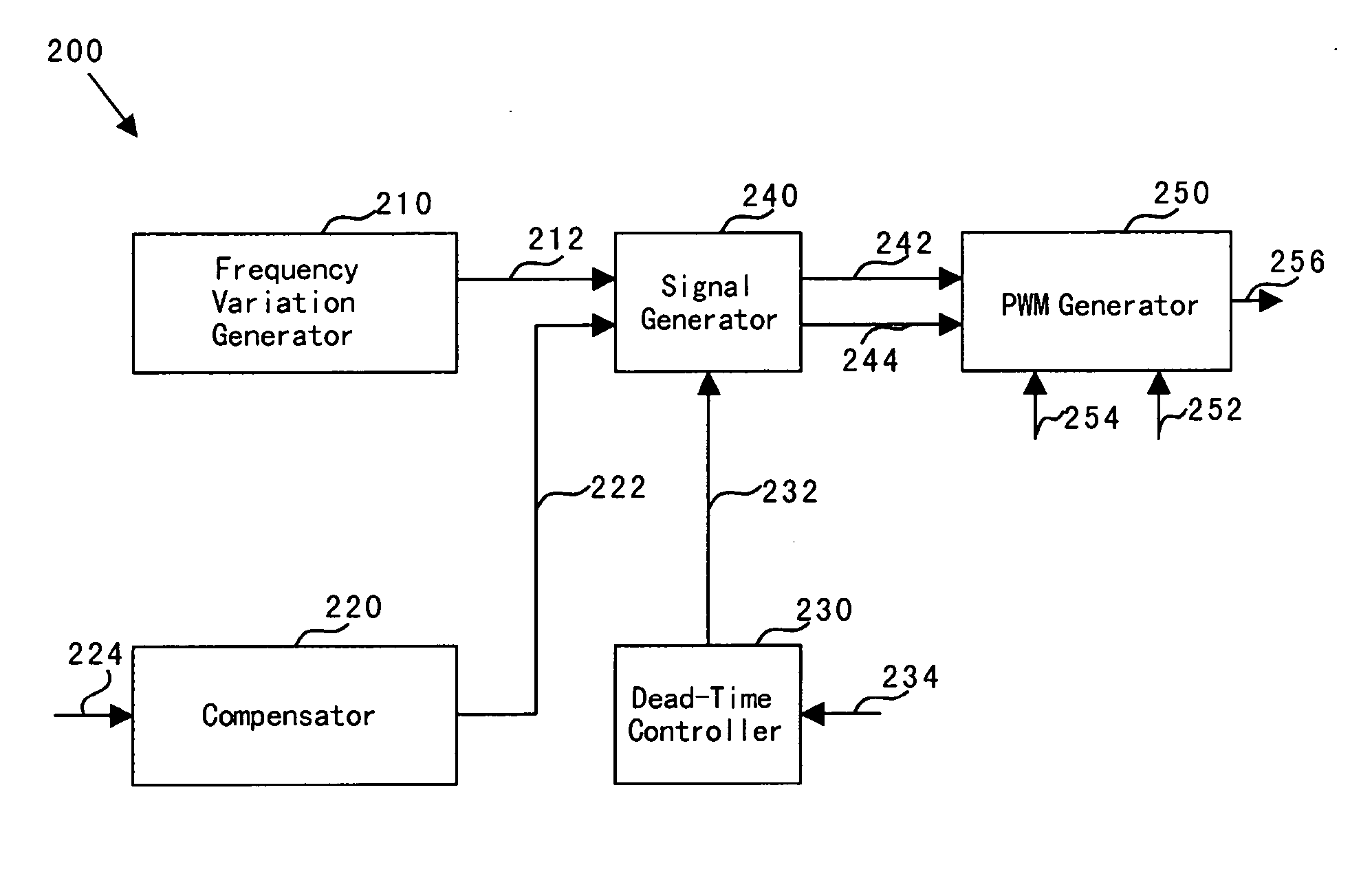
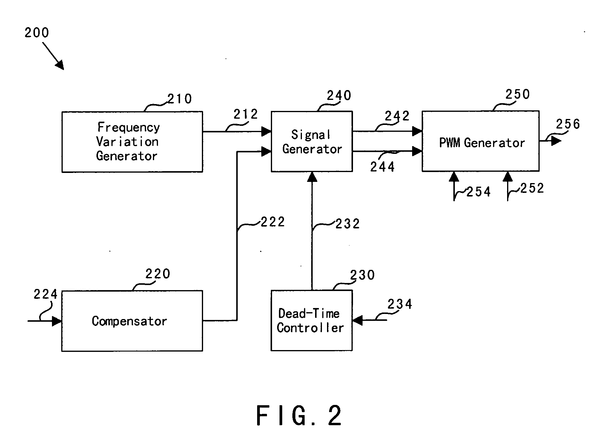
[0031]FIG. 2 is a simplified system for frequency control according to an embodiment of the present invention. This diagram is merely an example, which should not unduly limit the scope of the claims. One of ordinary skill in the art would recognize many variations, alternatives, and modifications. A system 200 includes a frequency variation generator 210, a compensator 220, a dead-time controller 230, a signal generator 240, and a pulse-width-modulation (PWM) generator 250. Although the above has been shown using a selected group of components for the system 200, there can be many alternatives, modifications, and variations. For example, some of the components may be ex...


PUM


Abstract

System and method for providing frequency control to a power converter. The system includes a controller configured to receive a load signal and generate a first control signal. The load signal indicates an output load for a power converter. Additionally, the system includes a signal generator configured to receive the first control signal and generates at least a first output signal. The first output signal is associated with a first signal strength and a first frequency. The first frequency is inversely proportional to a sum of a first time period, a second time period, and a third time period. The first signal strength increases with the time during the first time period, the first signal strength decreases with the time during the second time period, and the first signal strength is constant with respect to the time during the third time period.

Description

CROSS-REFERENCES TO RELATED APPLICATIONS [0001] This application claims priority to Chinese Patent Application No. 200510024385.6 (EastIP Ref. No. 05NI2016-1365-SMY), filed Mar. 11, 2005, entitled “System and Method for Adaptive Switching Frequency Control,” by Inventors Jun Ye, Zhen Zhu, Shifeng Zhao, Lieyi Fang, and Zhiliang Chen, commonly assigned, incorporated by reference herein for all purposes. [0002] The following two commonly-owned co-pending applications, including this one, are being filed concurrently and the other one is hereby incorporated by reference in its entirety for all purposes: [0003] 1. U.S. patent application Ser. No. ______, in the name of Jun Ye, Zhen Zhu, Shifeng Zhao, Lieyi Fang, and Zhiliang Chen, titled, “System and Method for Adaptive Switching Frequency Control,” (Attorney Docket Number 025748-000200US); and [0004] 2. U.S. patent application Ser. No. ______, in the name of Jun Ye, Zhen Zhu, Shifeng Zhao, Lieyi Fang, and Zhiliang Chen, titled, “System ...

Claims


Application Information

Patent Timeline
Patent Type & Authority Applications(United States)
IPC IPC(8): H04L12/50H04Q11/00H02M1/00
CPCH02M3/156H02M2001/0032H03K3/0231H04Q2213/1308H04Q2213/13098H04Q2213/1332Y02B70/16H02M1/0032Y02B70/10
Inventor YE, JUNZHU, ZHENZHAO, SHIFENGFANG, LIEYICHEN, ZHILIANG
Owner ON BRIGHT ELECTRONICS SHANGHAI
Why Eureka
Try Eureka