Large mode-area microstructure optical fiber
a microstructure, optical fiber technology, applied in the direction of optical waveguide light guide, instruments, optics, etc., can solve the problems of difficult to achieve single-mode propagation in such a large-diameter fiber with a conventional fiber design, limited maximum effective core area of single-mode optical fibers, and potential damage to single-mode fibers. achieve the effect of altering the waveguide mode properties of fibers
- Summary
- Abstract
- Description
- Claims
- Application Information
AI Technical Summary
Benefits of technology
Problems solved by technology
Method used
Image
Examples
example 1
Preparation of an Optical Fiber that Includes Axially Oriented Elements in the Core of the Optical Fiber
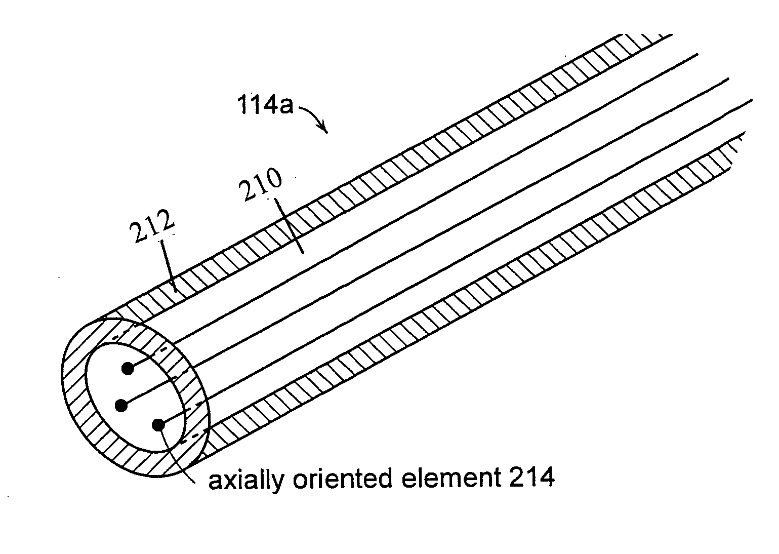
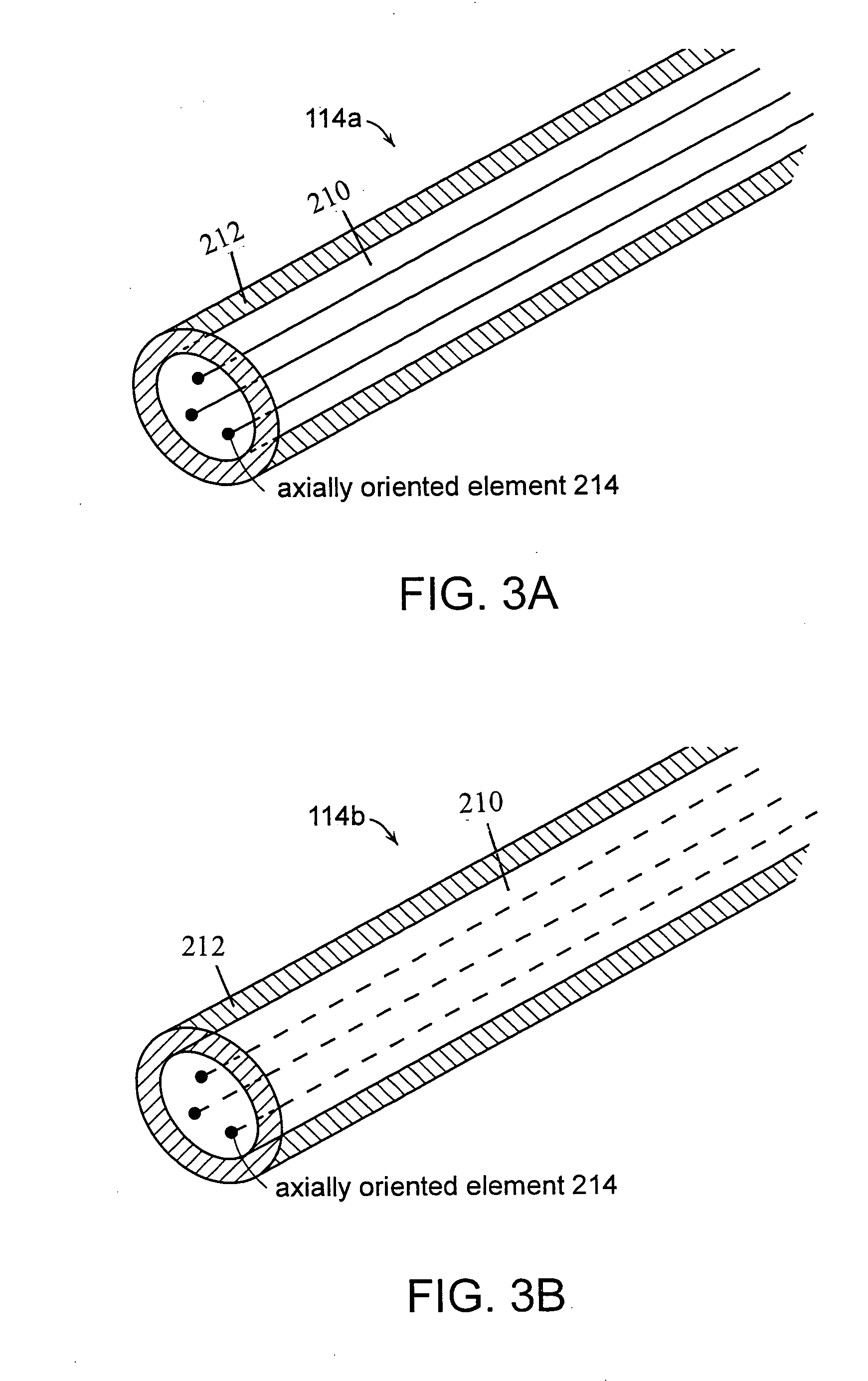
[0066] As shown in FIG. 8A-8B, an optical fiber incorporating three air voids (axially oriented elements) was prepared by drawing the optical fiber from a preform having three axially oriented structures, as shown in FIG. 7A. The core and cladding of the fiber were 29-micron and 125-micron in diameter, respectively. FIGS. 8A-8B show the same fiber with different microscope magnification. In FIG. 8A, three black dots represent the three air voids. In FIG. 8B, the three air voids appear as white dots. The air holds were 2-micron in diameter, and located 1 / 3.5 core diameter away from the core center.
example 2
Simulated Modes Profiles and Experimentally Measured Mode Profiles
[0067] For the optical fiber that includes three air holes, as described in Example 1, both numerical simulations and actual measurements were performed. The numerical simulations were done using the Beam Propagation Method.
[0068] An undoped optical fiber that includes three air voids as shown in FIG. 8A-8B was used for the experiment. The core of the fiber was 30-micron in diameter, and the length of the fiber was 1-meter. The fiber had NA of 0.085. The wavelength of a beam used for the experiment was 1-micron. For the equivalent optical fiber to that used for the experiment, parallel computational calculations of the symmetric fundamental (LP01) and first-order antisymmetric (LP11) modes were also performed. The calculated modes are shown in FIGS. 9A and 9B, respectively. As can be seen in FIGS. 9A-9B, the symmetric fundamental mode, LP01 (FIG. 9A), was modified only slightly from a near Gaussian profile, while th...
PUM
 Abstract
Description
Claims
Application Information
 - R&D
- Intellectual Property
- Life Sciences
- Materials
- Tech Scout
- Unparalleled Data Quality
- Higher Quality Content
- 60% Fewer Hallucinations
Browse by: Latest US Patents, China's latest patents, Technical Efficacy Thesaurus, Application Domain, Technology Topic, Popular Technical Reports.
© 2025 PatSnap. All rights reserved.Legal|Privacy policy|Modern Slavery Act Transparency Statement|Sitemap|About US| Contact US: help@patsnap.com


