DC brushless motor, light deflector, optical scanning device, and image forming apparatus
- Summary
- Abstract
- Description
- Claims
- Application Information
AI Technical Summary
Benefits of technology
Problems solved by technology
Method used
Image

Examples
first embodiment
[0070] [Light Deflector]
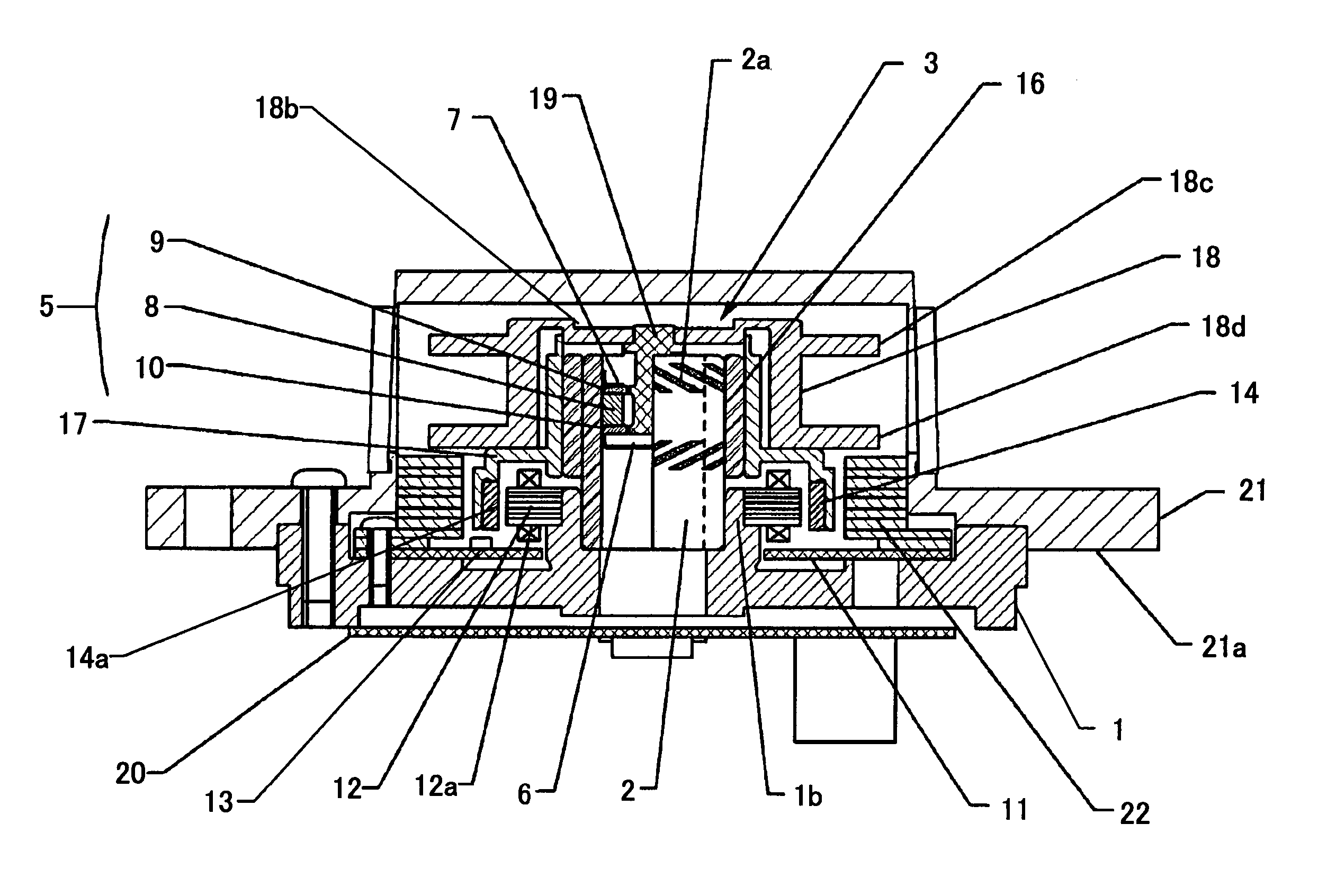
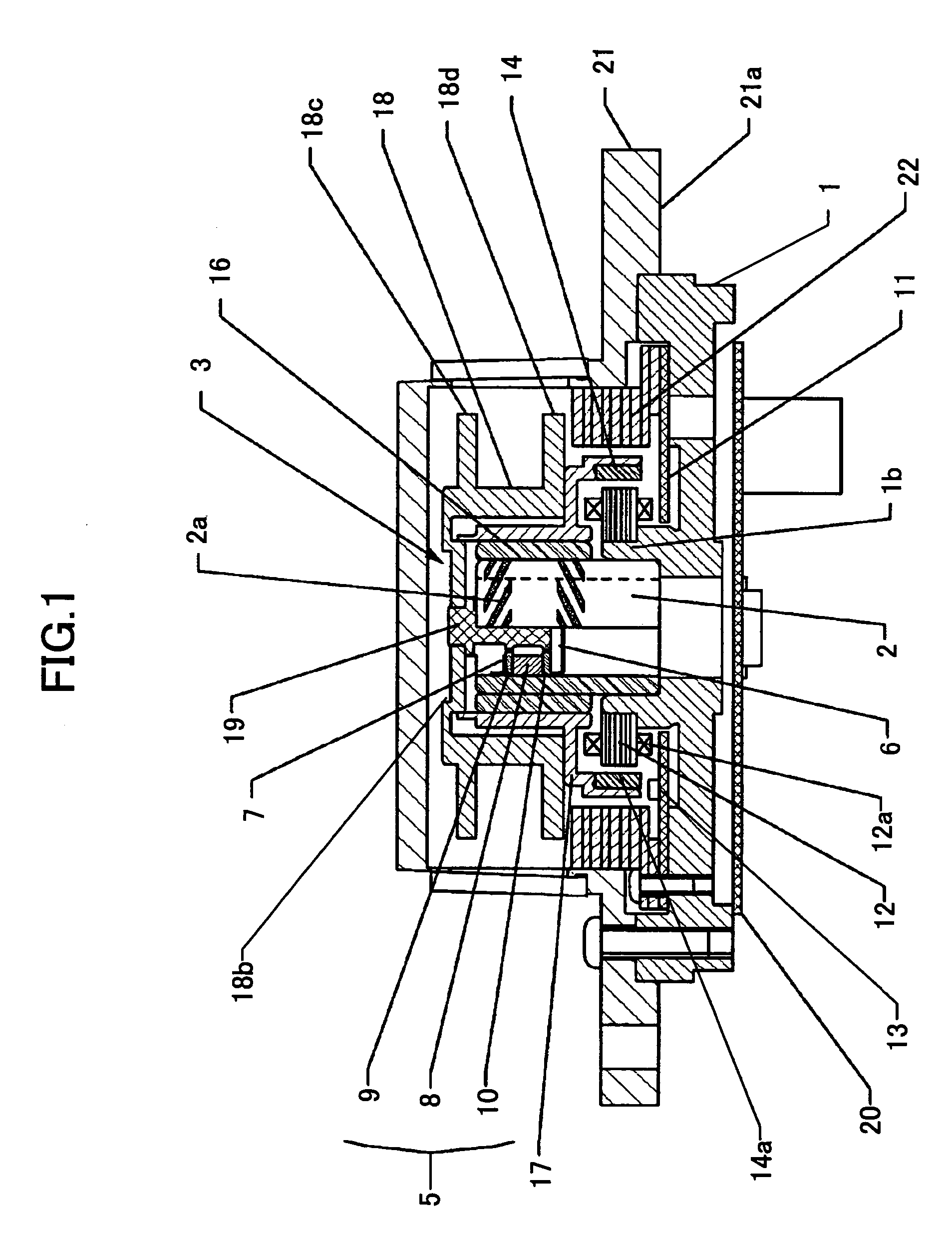
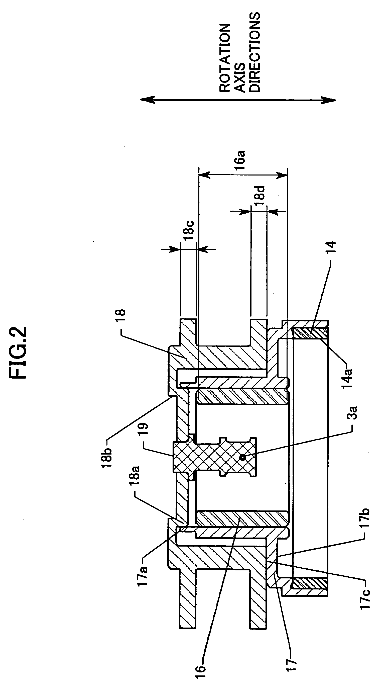
[0071]FIGS. 1 through 3 are diagrams showing a light deflector according to a first embodiment of the present invention. A description is given, with reference to FIGS. 1 through 3, of a configuration and an operation of the light deflector of the first embodiment. In this embodiment, a dynamic pressure air bearing for high-speed rotation is used as a bearing. Alternatively, bearings such as a dynamic pressure fluid bearing and a ball bearing may also be employed.
[0072] Referring to FIGS. 1 through 3, a reference surface 21a for attachment to an optics housing is formed on the lower surface of a cover case 21 of the light deflector. A housing 1 is fixed to the cover case 21. A through hole-like bearing attachment part 1b is formed in the center of the upper surface of the housing 1. A fixed shaft 2 forming a dynamic pressure bearing is fitted into and fixed to the bearing attachment part 1b. Multiple oblique grooves 2a for forming the dynamic pressure bearin...
second embodiment
[0131] [Optical Scanning Device]
[0132]FIG. 16 is a schematic diagram showing part of an optical scanning device according to a second embodiment of the present invention. The optical scanning device of this embodiment includes a light deflector according to one embodiment of the present invention. This optical scanning device is of a single beam type.
[0133] The optical scanning device according to this embodiment includes a light source 101, a coupling lens 102, an aperture 103, a cylindrical lens 104, a polygon mirror 105, lenses 106 and 107, a mirror 108, a photosensitive body 109, a mirror 110, a lens 111, and a light receiving element 112.
[0134] The light source 101 is a semiconductor laser device to emit light for optical scanning. The coupling lens 102 adapts the light emitted from the light source 101 to an optical system. The aperture 103 forms the light beam for optical scanning into a predetermined shape. The cylindrical lens 104 gathers the incident light beam in the su...
third embodiment
[0138] [Multi-beam Optical Scanning Device]
[0139]FIG. 17 is a schematic diagram showing part of an optical scanning device according to a third embodiment of the present invention. The optical scanning device of this embodiment includes a light deflector according to one embodiment of the present invention. This optical scanning device is of a multi-beam type. In FIG. 17, the same elements as those of FIG. 16 are referred to by the same numerals.
[0140] A light source 101A is a semiconductor laser array in which four light emission sources ch1 through ch4 are arranged at equal intervals in an array. In this embodiment, the light emission sources ch1 through ch4 are arranged in the sub scanning direction. Alternatively, the semiconductor laser array 101A may be inclined so that the direction of the light emission source array is inclined to the main scanning direction.
[0141] Referring to FIG. 17, each of four beams emitted from the four light emission sources ch1 through ch4, which ...
PUM
 Abstract
Description
Claims
Application Information