Image forming system employing effective optical scan-line control device
a control device and image forming technology, applied in the direction of recording devices, inking devices, instruments, etc., can solve the problems of scan line bending phenomenon, inability to achieve perfect f characteristics,
- Summary
- Abstract
- Description
- Claims
- Application Information
AI Technical Summary
Benefits of technology
Problems solved by technology
Method used
Image
Examples
first embodiment
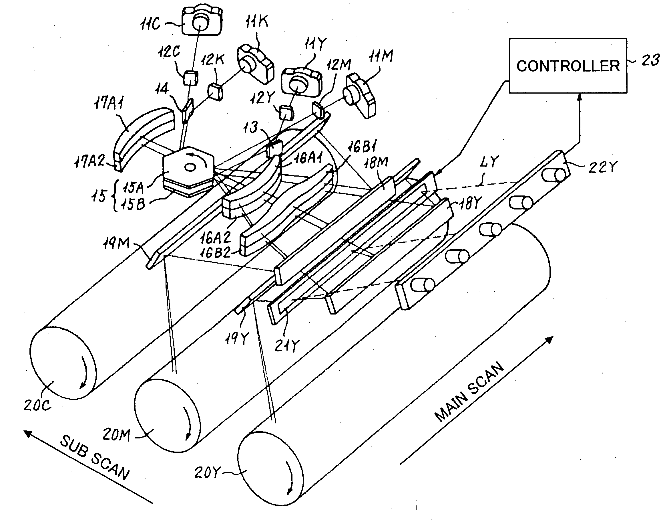
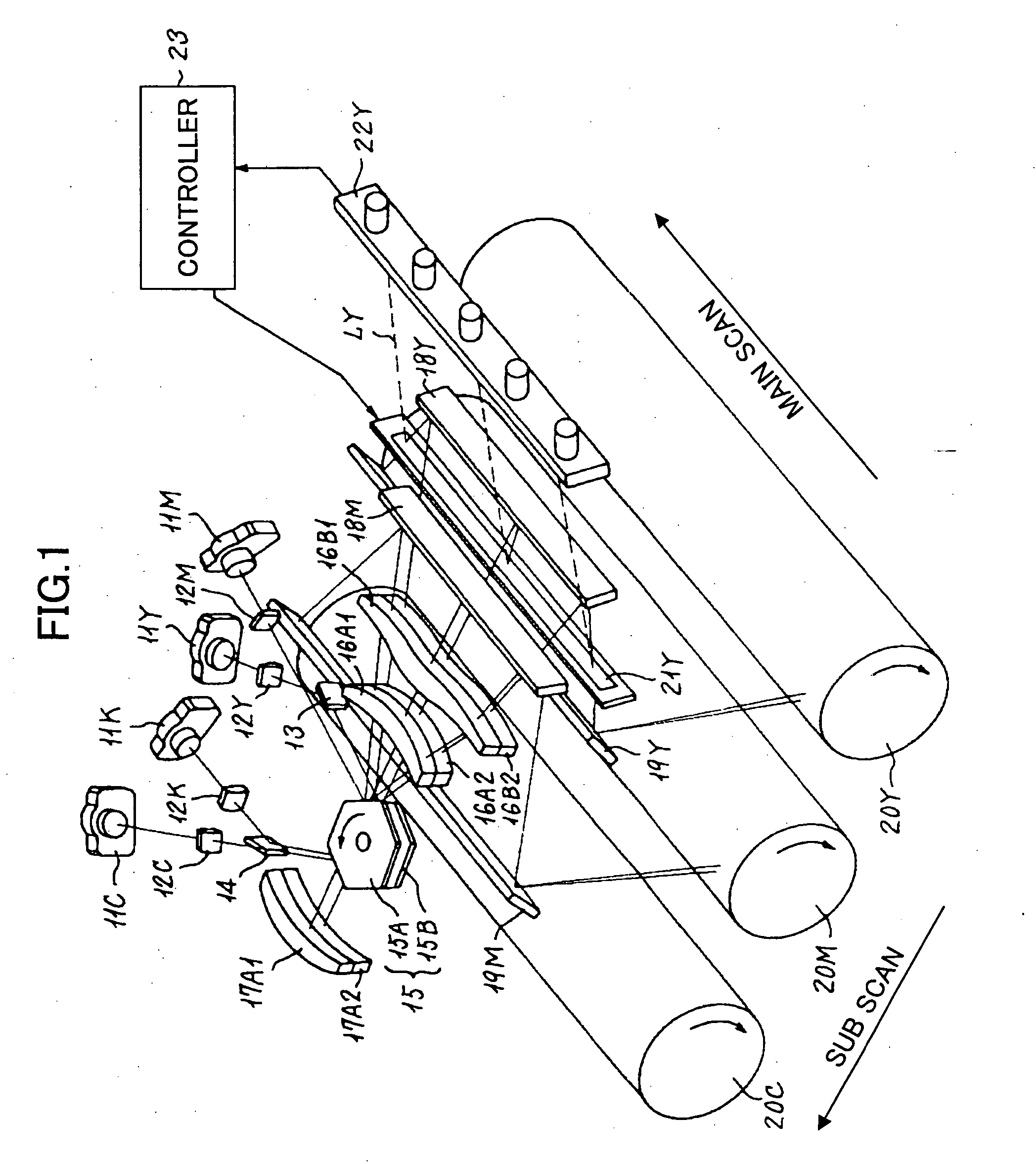
[0103] According to the present invention described above, since the scan line bending of the optical spot performing the optical scanning for every photoconductor is detected, even when a change occurs in the scan line bending resulting from a change in the characteristics of the fθ lens due to aging, environmental change or so arises, proper scan line bending correction can be achieved at any time.
[0104] The scan line bending state may be detected before the color image formation process is performed each time, or may be detected at predetermined intervals, i.e., once a day, every three days, or the like, or, may be performed on an input operation by a users. In case the color image formation process is repeated successively, change in the scan line bending state resulting from temperature rise inside the machine occurring due to the continuation image formation process can be coped with by carrying out the detection of the scan line bending state once, or several time per every i...
second embodiment
[0144] In the second embodiment shown in FIG. 7, the scanning image-formation optical system of fθ lens is provided for each of the four deflected beams coming from the two polygon mirrors 51 and 52. Thus, total 4 sets of fθ lenses are provided, each including two lenses. These 4 sets of fθ lenses are optically equivalent mutually, and the optical path length toward the relevant photoconductor from each light source device is also set up equally. Moreover, each fθ lens is held respectively at a plate PTY, PTM, PTC, or PTK, and is fixed to an optical housing 75. Each plate touches the relevant lenses by the whole or partial surfaces thereof.
[0145] The lenses LNY1, LNM1, and LNC1 are made of a same resin material, and, also, the lenses LNY2, LNM2, and LNC2 are made of a same resin material. As these materials, a polycarbonate, or a synthetic resin which includes a polycarbonate as a main ingredient thereof superior in low water absorptivity, high transparency, and fabrication easiness...
third embodiment
[0159] As the scan line bending detection device, the same described above with reference to FIGS. 5A through 5D may be applied. However, it is also possible to apply a scheme which will be described in the description of the present invention shown in FIG. 10A, instead. FIGS. 8A and 8B illustrate one example of a mode of correcting scan lines according to the above-mentioned aspect of the present invention.
[0160]FIG. 8A shows each scan line (state in which it is visualized and transferred onto a common medium) detected by the scan line deviation detection device. ‘K’ denotes a scan line of a beam which writes a black component image; ‘C’ denotes a scan line of a beam which writes a cyan color component image; ‘Y’ denotes a scan line of a beam which writes in a yellow color component image; and ‘M’ denotes a scan line of a beam which writes a magenta color component image.
[0161] In FIG. 8A, each of the scan lines Y, M, C, and K has a scan line bending, and also, is shifted relative...
PUM
 Abstract
Description
Claims
Application Information
 - R&D
- Intellectual Property
- Life Sciences
- Materials
- Tech Scout
- Unparalleled Data Quality
- Higher Quality Content
- 60% Fewer Hallucinations
Browse by: Latest US Patents, China's latest patents, Technical Efficacy Thesaurus, Application Domain, Technology Topic, Popular Technical Reports.
© 2025 PatSnap. All rights reserved.Legal|Privacy policy|Modern Slavery Act Transparency Statement|Sitemap|About US| Contact US: help@patsnap.com


