Supercharge Your Innovation With Domain-Expert AI Agents!

Multi-stage optical amplifier optimized with respect to noise, gain and bandwidth

a multi-stage, optical amplifier technology, applied in the direction of optical transmission with multiple stages, electromagnetic transmission, transmission, etc., can solve the problems of low noise, high gain, wide bandwidth, and difficult to achieve in a single optical amplifier, so as to improve noise, reduce noise, and increase the effect of gain

Inactive Publication Date: 2006-09-21
TELECOM ITALIA SPA
View PDF27 Cites 9 Cited by
  • Summary
  • Abstract
  • Description
  • Claims
  • Application Information

AI Technical Summary

Benefits of technology

[0017] It is known that the noise figure of a two-stage amplifier is dominated by the noise figure of the first stage of the amplifier. Applicants have observed that the use of a first amplifying stage of a multi-stage optical amplifier comprising a rare-earth doped silica-based optical fiber reduces the noise figure, especially in the C-band wavelength region. Preferably, the first stage of the amplifier is pumped in the 980 nm band. More preferably, the rare-earth doped silica-based optical fiber is an Er-doped silica-based fiber (EDSF). Even more preferably, the rare-earth doped silica-based optical fiber is pumped in a forward direction to the transmission signal to improve the noise figure over the whole C-band, without a corresponding degradation in the L-band. Applicants have observed a noise figure of less than 5 dB in the 1545-1570 nm wavelength region for a two-stage configuration in which the first stage comprises a EDSF pumped at about 980 nm and the second stage comprises a Er-doped tellurite-based fiber (EDTF) bi-directionally pumped at 1480 nm.
[0018] In the L-band, the achievable gain per unit length is typically lower than in the C-band, especially in silica hosts. Tellurite fiber hosts generally provide a larger gain in the L-band. Applicants have noticed that in EDTFAs the gain in the L-band remains however significantly lower than that of the C-band. They have surprisingly found that the addition of an amplification stage comprising a silica-based fiber, which is located at the output of an amplification stage comprising an EDTF, leads to a significant increase of the output power across the C-band and also in the L-band.
[0026] In order to achieve a flattened gain in the C- and L-bands, it is preferable to include a gain equalizing filter (GEF) at the output of the amplification stage comprising the EDTF. The effect of the GEF is to reduce the maximum gain excursion between the C- and the L-band by cutting part of the gain in the C-band. It is to be understood that the increase of optical gain in the L-band due to the amplification stage comprising a silica-based fiber at the output of the amplification stage comprising an EDTF will improve the overall performance of the amplifier, also with gain equalization.

Problems solved by technology

However, wide bandwidth, low noise and high gain are usually difficult to achieve within a single optical amplifier.
However, by using silica-based EDFA, there is a dip in the amplification band of the parallel configuration at around 1565 nm, i.e. approximately between the C- and L-bands, because of band-coupling, making the amplification less efficient.
One technical problem arising in connection with the usage of the EDTFA is that its noise figure (NF) in the C-band wavelength region with 1480 nm pumping is higher than that of an Er-doped silica fiber (EDSF) amplifier pumped at 980 nm.
Consequently, 980 nm band pumping of an EDTFA results often inefficient for many of the newly developed or commercially available tellurite-based optical fibers.
Splicing of a non-silica fiber, such as a tellurite fiber, to a silica fiber, from which regular transmission fibers are made, is generally cumbersome if relatively low splice losses are sought.
Silica glasses and non-silica glasses typically exhibit highly different thermal characteristics, indeed the gap between the respective softening temperatures can exceed 1000° C., so that they cannot be jointed by conventional arc fusion splicing techniques.
This means that it is rather complex and time consuming to realize low loss joints between transmission fibers and non-silica fibers, such as tellurite fibers.
Applicants have noted that in order to realize a fiber amplifier including a tellurite-based fiber with a good noise figure, pumping in the 1480 nm absorption band in a first stage of the amplifier is less desirable.

Method used


Image

  • Multi-stage optical amplifier optimized with respect to noise, gain and bandwidth
  • Multi-stage optical amplifier optimized with respect to noise, gain and bandwidth
  • Multi-stage optical amplifier optimized with respect to noise, gain and bandwidth

Examples


Embodiment Construction

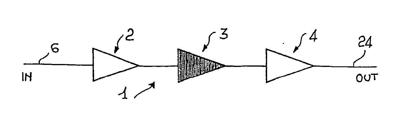
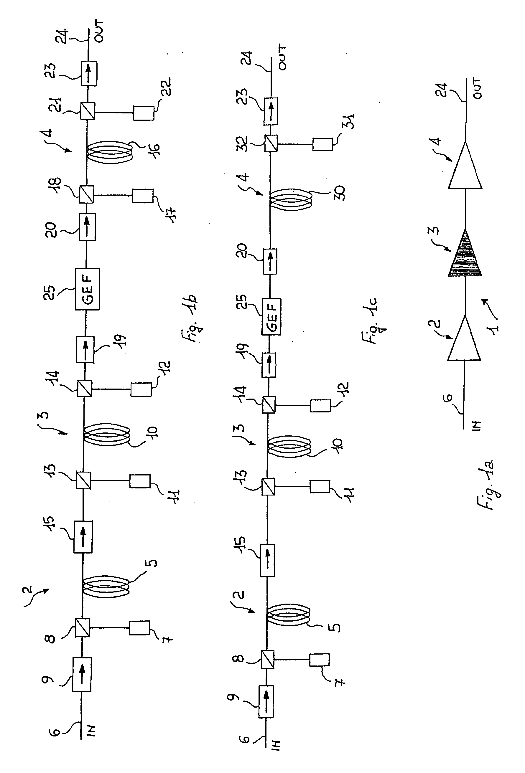
[0041] With reference to FIG. 1a, 1 indicates a three-stage optical amplifier according to an embodiment of the present invention. In particular, an amplifying stage includes a length of amplifying optical fiber associated to at least a pumping source. The optical amplifier 1 comprises a first 2, a second 3 and a third 4 amplification stage connected in series in said order. The three-stage optical amplifier 1 receives at an input in an optical signal 6 to be amplified and outputs at an output OUT the amplified output optical signal 24. The input optical signal 6 includes at least a signal wavelength λS. Preferably, the optical signal carries a number of optical channels λS1, . . . , λSn, comprised between about 1530 nm and 1625 nm, which corresponds approximately to the C- and L-bands. For example, in case of 50 GHz standard ITU-T DWDM channel spacing, the wavelength of the first channel will be 1528.38 nm (corresponding to 196.15 THz in frequency), while the wavelength of the last...


PUM


Abstract

A multi-stage optical amplifier for a fiber-optic transmission system, in particular, an amplifier having a multi-stage configuration that allows an optimization of its performance with respect to noise, gain and bandwidth. The multi-stage amplifier has a first amplifying stage including a rare-earth doped optical active fiber; a second amplifying stage connected to the first amplifying stage, the second amplifying stage including a tellurite-based active fiber doped with a rare earth element; and a third amplifying stage connected with the second amplifying stage, the third amplifying stage including a silica-based fiber.

Description

TECHNICAL FIELD [0001] The present invention relates to a multi-stage optical amplifier for a fiber-optic transmission system, in particular to an amplifier having a multi-stage configuration that allows an optimization of its performance with respect to noise, gain and bandwidth. TECHNOLOGICAL BACKGROUND [0002] In telecommunication fiber-optic transmission systems, such as wavelength division multiplexing (WDM), a plurality of optical signals of different wavelengths is transmitted through a single optical fiber. In these systems, amplification is often needed according to the distance over which optical signals should be transmitted to and it can be performed by means of optical amplifiers. [0003] In order to increase the capacity of WDM systems, i.e., the number of available signal channels, optical amplifiers with broad amplification bandwidth and high output power are necessary. In addition, high gain, so that longer distances can be travelled by the signals (thus reducing the ...

Claims


Application Information

Patent Timeline
IPC IPC(8): H01S3/00H04B10/294
CPCH04B10/294H04B2210/003
Inventor CAPONI, RENATOPAGANO, ANNACHIARAPOTENZA, MARCELLOSORDO, BRUNO
Owner TELECOM ITALIA SPA
Features
  • R&D
  • Intellectual Property
  • Life Sciences
  • Materials
  • Tech Scout
  • Unparalleled Data Quality
  • Higher Quality Content
  • 60% Fewer Hallucinations
Learn More