DC converter

a converter and direct current technology, applied in the direction of electric variable regulation, process and machine control, instruments, etc., can solve the problems of deteriorating efficiency, synchronous rectification and power source efficiency efficiency, and synchronous rectifier chattering, so as to achieve stably driving and improve efficiency

Inactive Publication Date: 2006-09-21
SANKEN ELECTRIC CO LTD
View PDF6 Cites 36 Cited by
  • Summary
  • Abstract
  • Description
  • Claims
  • Application Information

AI Technical Summary

Benefits of technology

[0065] According to the present invention, DC converter capable of stably driving synchronous rectifiers and improving efficiency can be provided.

Problems solved by technology

Instead, currents are passed through the diodes D10 and D11 during the periods, thereby deteriorating the efficiency of synchronous rectification and the efficiency of a power source.
This results in causing the chattering of the synchronous rectifiers and deteriorating efficiency.
Adding the CR snubber circuits to suppress the chattering will increase losses and deteriorate efficiency.

Method used


Image

  • DC converter
  • DC converter
  • DC converter

Examples


first embodiment

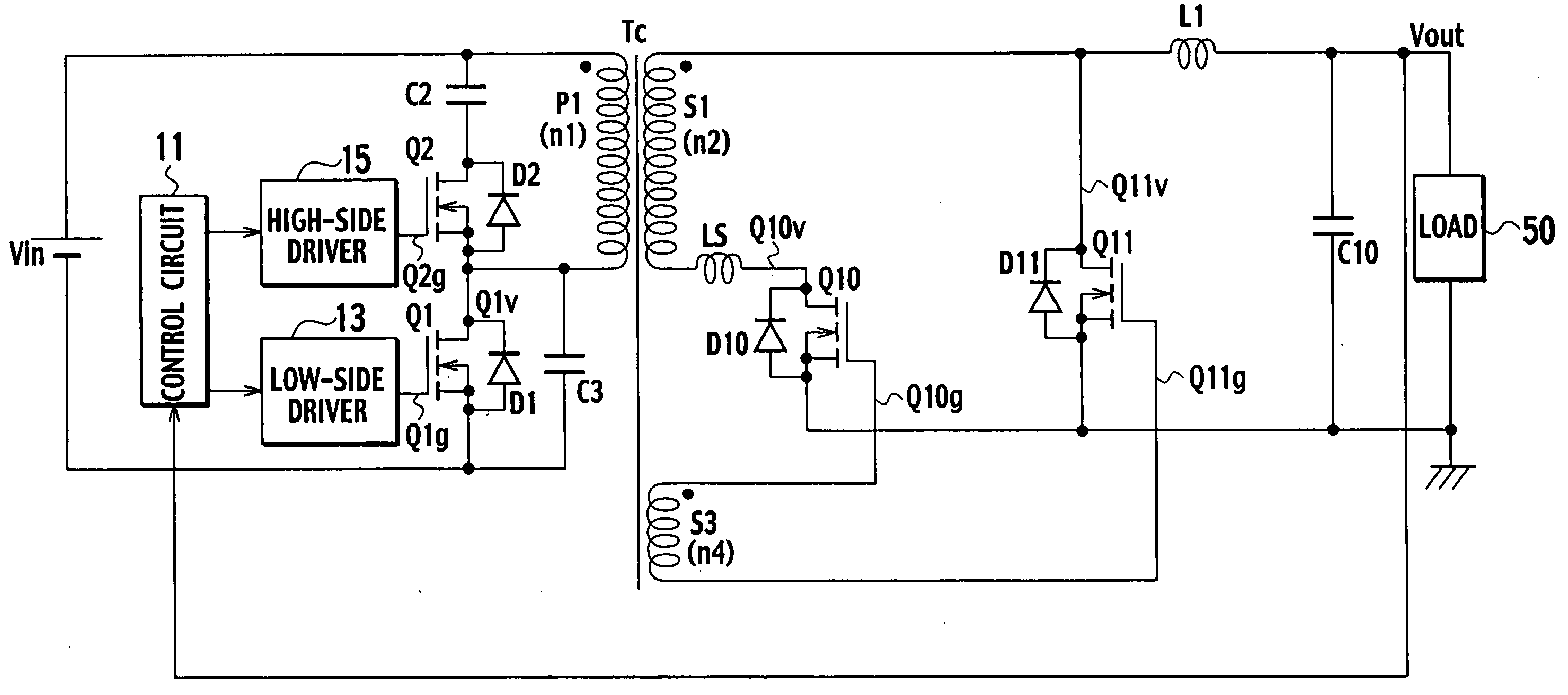
[0081]FIG. 8 is a circuit diagram showing a DC converter according to the first embodiment of the present invention. The first embodiment will be mainly explained in connection with parts that are different from those of the DC converter of FIG. 1.

[0082] A transformer Tc has a primary winding P1 (having the number of turns of n1), a secondary winding S1 (having the number of turns of n2) loosely coupled with the primary winding P1, and a tertiary winding S3 (having the number of turns of n4) tightly coupled with the primary winding P1. To turn on a switch Q10 when a switch Q1 is ON, the winding start of the tertiary winding S3 is connected to the gate of the switch Q10. To turn on a switch Q11 when the switch Q1 is OFF, the winding end of the tertiary winding S3 is connected to the gate of the switch Q11.

[0083] A voltage generated by the tertiary winding S3 is applied to the gates of the switches Q10 and Q11, to drive the switches Q10 and Q11. The tertiary winding S3 is tightly co...

second embodiment

[0110]FIG. 10 is a circuit diagram showing a DC converter according to the second embodiment of the present invention. In addition to the structure of the first embodiment shown in FIG. 8, the second embodiment employs a capacitor C22, i.e., a first capacitor between the winding start of a tertiary winding S3 and the gate of a switch Q10.

[0111] The capacitor C22 may be arranged between the winding end of the tertiary winding S3 and the gate of a switch Q11.

[0112] The DC converter according to the second embodiment provides the same effects as those of the DC converter of the first embodiment. In addition, the capacitance of the additional capacitor C22 is connected in series with the input capacitance (not shown) of switches Q10 and Q11 that are MOSFETs serving as synchronous rectifiers. Even if the tertiary winding S3 generates a voltage higher than the withstanding voltage of the drive terminal (gate) of each synchronous rectifier, a drive terminal voltage of the synchronous rec...

third embodiment

[0115]FIG. 11 is a circuit diagram showing a DC converter according to the third embodiment of the present invention. Parts of the third embodiment that are different from those of the related art of FIG. 3 will be explained.

[0116] A transformer Td of the third embodiment has a primary winding (having the number of turns of n1), a first secondary winding S1 (having the number of turns of n2) very loosely coupled with the primary winding P1, a second secondary winding S2 (having the number of turns of n3) loosely coupled with the primary winding P1, and a tertiary winding S3 (having the number of turns of n4) tightly coupled with the primary winding P1.

[0117] To turn on a switch Q10 when a switch Q1 is ON, the winding start of the tertiary winding S3 is connected to the gate of the switch Q10. To turn on a switch Q11 when the switch Q1 is OFF, the winding end of the tertiary winding S3 is connected to the gate of the switch Q11.

[0118] A voltage generated by the tertiary winding S3...


PUM


Abstract

A DC converter has a transformer with loosely coupled primary and secondary windings, a main switch connected in series with the primary winding of the transformer, and a series circuit connected to ends of one of the primary winding and main switch. The series circuit includes a clamp capacitor and an auxiliary switch. The main and auxiliary switches are alternately turned on/off so that a voltage of the secondary winding of the transformer is synchronously rectified with synchronous rectifiers and is smoothed with smoothing elements, to provide a DC output. The DC converter also includes a tertiary winding provided for the transformer, tightly coupled with the primary winding, and configured to generate a voltage that drives the synchronous rectifiers.

Description

BACKGROUND OF THE INVENTION [0001] 1. Field of the Invention [0002] The present invention relates to a highly efficient DC (direct current) converter. [0003] 2. Description of the Related Art [0004]FIG. 1 is a circuit diagram showing a DC converter according to a related art. The DC converter shown in FIG. 1 is a forward converter provided with active clamps. The DC converter includes a DC power source Vin and a main switch Q1 such as a MOSFET (field effect transistor) connected to the DC power source Vin through a primary winding P1 (having the number of turns of n1) of a transformer Ta. [0005] Ends of the primary winding P1 are connected to a series circuit that consists of an auxiliary switch Q2 such as a MOSFET and a clamp capacitor C2. The series circuit consisting of the switch Q2 and clamp capacitor C2 forms an active clamp circuit, which may be connected in parallel with the switch Q1. [0006] A diode D1 is connected between the drain and source of the switch Q1, and a diode ...

Claims


Application Information

Patent Timeline
Patent Type & Authority Applications(United States)
IPC IPC(8): H02M3/335
CPCH02M3/33592Y02B70/1475Y02B70/10A44B18/0073A63B71/10A63B71/1291A63B2071/105
Inventor ASO, SHINJITSURUYA, MAMORUSATO, MAKOTO
Owner SANKEN ELECTRIC CO LTD
Why Eureka
Try Eureka