
Integrated volume holographic optical circuit apparatus

a holographic optical circuit and integrated volume technology, applied in the field of optical (or fiber optical) systems, can solve the problems of difficult manufacturing, insertion loss of several decibels, and large increase in the size of the component package, so as to optimize optical performance and reliability, and reduce the number of optical fiber connections

Active Publication Date: 2006-09-21
LOCKHEED MARTIN CORP
View PDF24 Cites 24 Cited by
  • Summary
  • Abstract
  • Description
  • Claims
  • Application Information

AI Technical Summary

Benefits of technology

[0009] The present disclosure is directed to an optical apparatus that provides multiplexing and de-multiplexing functions in a space saving circuit structure with a reduced number of necessary optical fiber connections to optimize optical performance and reliability. The optical apparatus includes an integrated structure that can provide both multiplexing and de-multiplexing functions so the apparatus can act as an optical transceiver. Also, the apparatus is able to function over a wide temperature range, which permits the use of multiplexing and de-multiplexing in environments that were previously limited to one photonic signal per fiber.

Problems solved by technology

As the number of channels increase, circuits using TFFs dramatically increase in both the size of the component package and the fabrication complexity of the circuits.
AWGs are well suited to provide a large number of channels, but have a limited ability to tailor passband and efforts to flatten the passband have resulted in insertion loss of several decibels.
AWGs are also relatively delicate devices that can be rendered inoperable if mishandled or subject to extreme conditions, and are relatively difficult to manufacture because of their low yield rate.
Regardless of the components used, the above-described circuit structures suffer from disadvantages.
The connections can cause losses in the signal between components and are prone to mechanical failure.
The footprint of assembled circuit structures is limited by the minimum bending diameter (approximately 5-centimeter) required for long-term mechanical reliability of standard telecommunications fiber.
Many of the multiplexer devices are not suited for a wide range of temperatures, and the optical fiber connections tend to degrade in extreme conditions for all of the above structures.
Also, temperature changes cause wavelength drifts that prevent the use of multiplexing devices in extreme conditions.
Optical circuits used in such extreme conditions are often limited to one photonic signal per fiber, which increases costs, complexity, maintenance, and space requirements.

Method used


Image

  • Integrated volume holographic optical circuit apparatus
  • Integrated volume holographic optical circuit apparatus
  • Integrated volume holographic optical circuit apparatus

Examples


Embodiment Construction

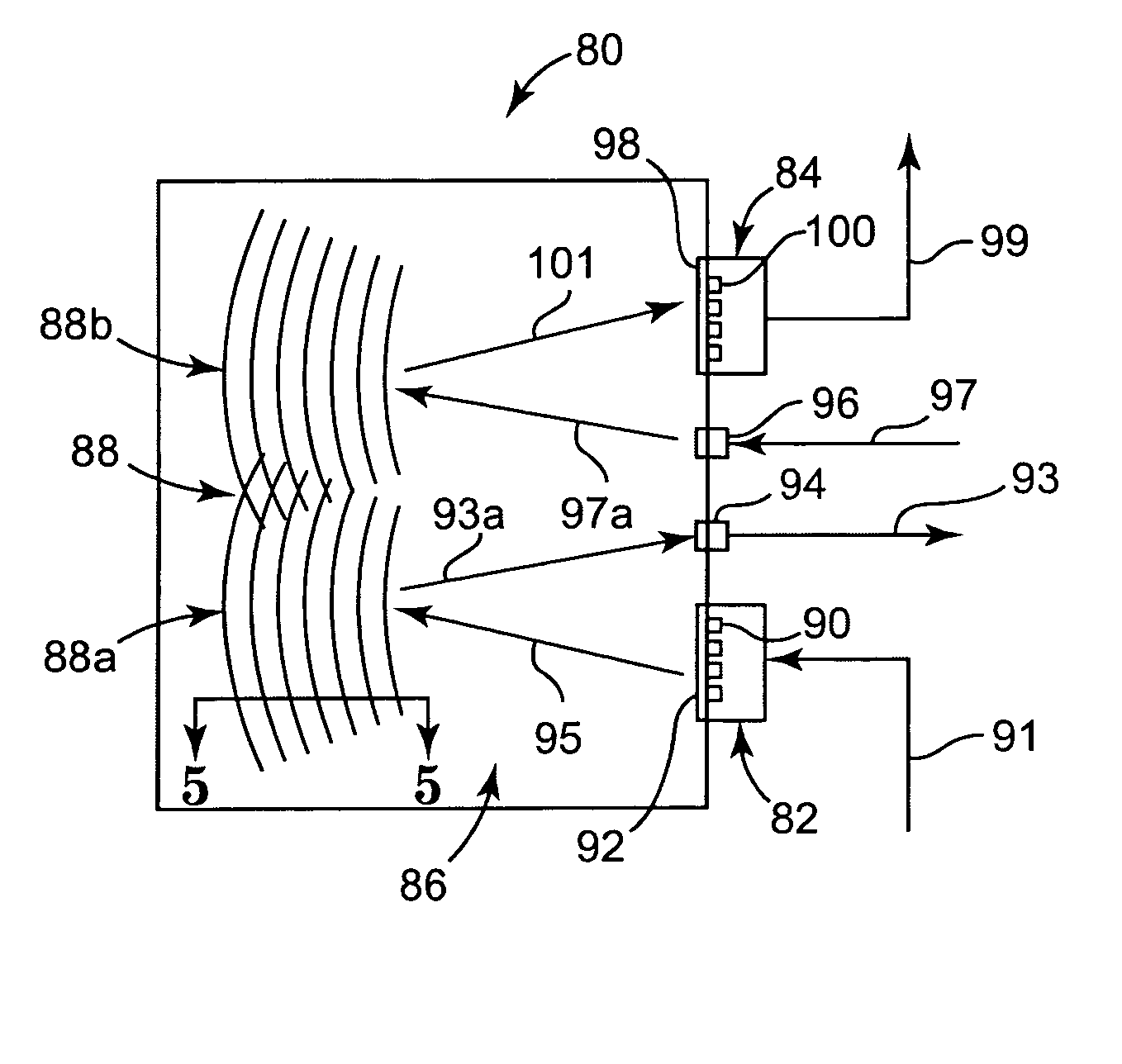
[0020] This disclosure relates to optical circuit components for use with optical systems. The disclosure, including the figures, describes the circuit components and their parts with reference to several illustrative examples. For example, the present disclosure proceeds with respect to the particular transceiver described below. However, it should be noted that the present invention could be implemented in other circuit components, such as receivers or transmitters, as well. The present disclosure proceeds with respect to the transceiver for illustrative purposes only. Other examples are contemplated and are mentioned below or are otherwise imaginable to someone skilled in the art, including other circuit components as well. The scope of the invention is not limited to the few examples, i.e., the described embodiments of the invention. Rather, the scope of the invention is defined by reference to the appended claims. Changes can be made to the examples, including alternative desig...


PUM


Abstract

The present disclosure is directed to an optical apparatus suitable for coupling to an optical network. The optical apparatus is adapted to transmit multiplexed optical signals on the optical network and / or de-multiplex optical transmissions from the network. The optical apparatus includes an optical waveguide and an optoelectronic device. The optical waveguide has a set of diffractive elements in the form of a scribed volume hologram, which provides an optical transfer function. The optical waveguide also includes a first optical port and a second optical port. The second optical port is adapted to be optically coupled to the optical network. The optoelectronic device includes a plurality of optical portions. The optoelectronic device is adapted to convert optical signals at the optical portions into electric signals and / or convert electric signals into optical signals at the optical portions.

Description

BACKGROUND [0001] The present disclosure is directed to circuit components in optical (or fiber optical) systems. More particularly, the present disclosure is directed to integrated photonic transmitters, receivers, and transceivers providing a wavelength division multiplexer or de-multiplexer with a volume holograph waveguide adapted for use in optical, or photonic, circuits. [0002] Fiber optical systems generally refer to the medium and technology associated with the transmission of signals in the form of light pulses, or photons, along a glass or plastic fiber. Optical systems are distinguishable from electrical systems using conventional electrically conductive wires, such as copper wire, in the transmission of electrical signals. Optical systems also include advantageous capabilities over electrical systems. For example, electrical signals interact with each other and their environment. This results in a need for non-intersecting and spaced-apart electrical wire links between e...

Claims


Application Information

Patent Timeline
Patent Type & Authority Applications(United States)
IPC IPC(8): G02B6/12
CPCG02B6/29326G02B6/29328G02B6/4206G02B6/4246G02B6/4249G02B2006/12107G03H1/0005
Inventor UHLHORN, BRIAN L.STEVENS, RICK C.WHALEY, GREGORY J.KRAWCZAK, JOHN A.
Owner LOCKHEED MARTIN CORP
Features
  • Generate Ideas
  • Intellectual Property
  • Life Sciences
  • Materials
  • Tech Scout
  • Unparalleled Data Quality
  • Higher Quality Content
  • 60% Fewer Hallucinations
Learn More